Laparoscopic camera navigation trainer

a technology for navigation trainers and laparoscopic cameras, applied in educational models, instruments, educational appliances, etc., can solve the problems of poor performance of camera navigators, loss of direct control, and increasing criticality of angled laparoscope use, so as to achieve more efficient laparoscopic navigation

Active Publication Date: 2010-09-28
THE ADMINISTRATORS OF THE TULANE EDUCATIONAL FUND
View PDF12 Cites 60 Cited by
  • Summary
  • Abstract
  • Description
  • Claims
  • Application Information

AI Technical Summary

Benefits of technology

[0020]The system and method disclosed herein effectively train novices for laparoscopic camera navigation.

Problems solved by technology

However, this direct control is lost in the performance of laparoscopic surgery as the visualization becomes dependant on the ability of the assistant to navigate the laparoscope.
As laparoscopic procedures have become more complex and have moved from one-quadrant procedures to multi-quadrant procedures, use of the angled laparoscope has become increasingly more critical.
This can lead to a poor performance by the camera navigator causing frustration for both the camera navigator and the surgeon.
Studies regarding the use of these robotic systems have met with mixed results.
Laparoscopic camera navigation is often considered the easiest and least important task in the operating room but it can be difficult to master and includes the same barriers described in laparoscopic instrument manipulation, namely, the fulcrum effect (Gallagher, 1998), fixed access points (Jordan, 2001), a 2-demensional environment (Jones, 1996) and decreased range of motion.
The difficulty in skill acquisition is enhanced when an angled laparoscope is utilized.
The rotation of the lens independent of the camera gives the ability to “look around corners” but to use this additional degree of freedom without change of horizon, steadiness or field of view is not intuitive and may be counter intuitive as moving the light cord up points the lens angle down.
Since camera navigation is perceived to be an easy task, the least experienced person in the operating room is often charged with this duty, which can lead to frustration.
This frustration is compounded when the camera operator changes between cases, as is seen both in the academic arena with medical students rotating and in the private sector with different operating room technicians.
Because of this inexperience, training usually occurs in the operating room but this has been shown to be inefficient and costly.
Despite this, training of camera navigation is not a laparoscopic skill widely taught outside of the operating room and there is no data, other than little virtual reality data (Hyltander, 2002) (Haluck, 2001), regarding training in laparoscopic camera navigation skills.
However, these platforms have limitations including a hardware interface found to be inadequate for camera navigation simulation by 86% of subjects (Haluck, 2001).
Additionally, a virtual reality platform would not allow camera navigation to be taught in some settings due to setup costs.

Method used


Image

  • Laparoscopic camera navigation trainer
  • Laparoscopic camera navigation trainer
  • Laparoscopic camera navigation trainer

Examples


Embodiment Construction

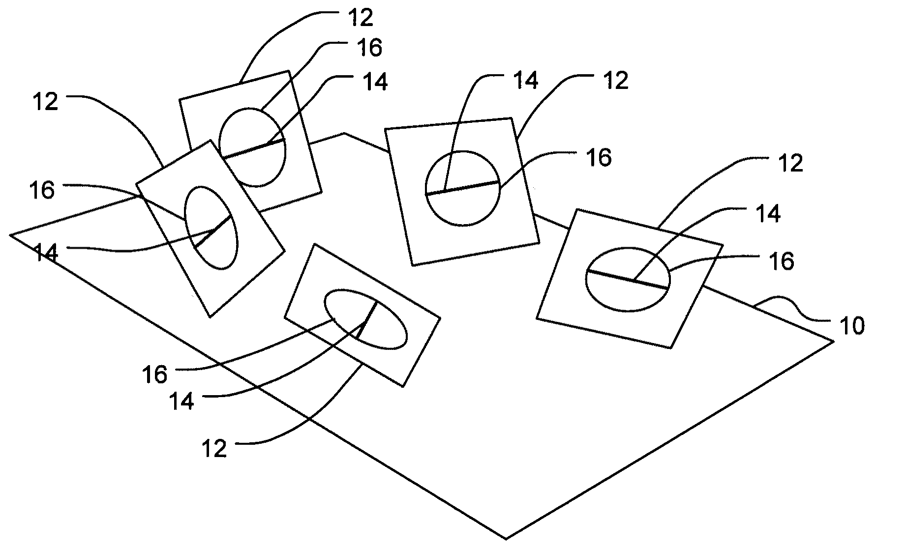
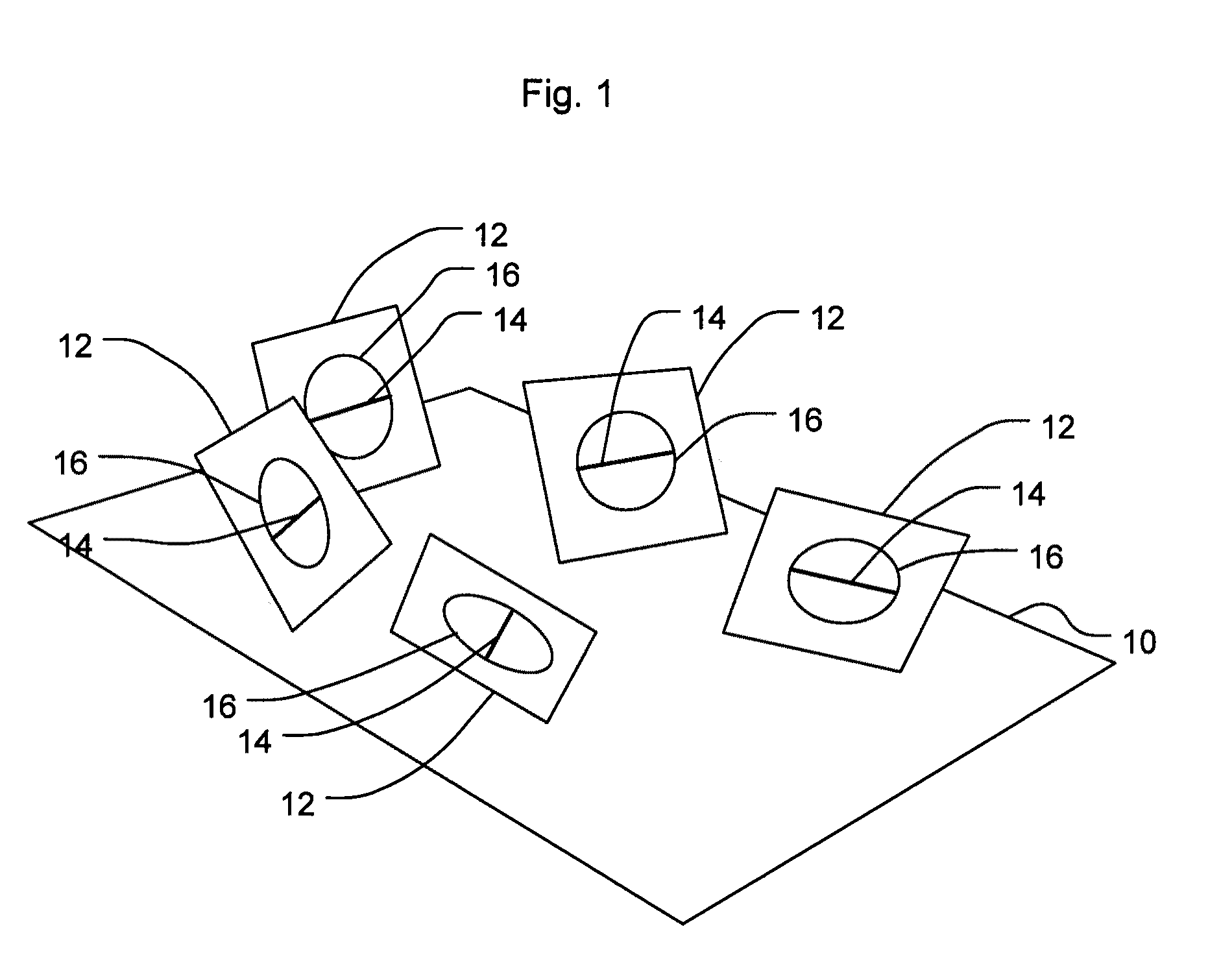
[0028]Embodiments for the system and method of the invention are usable for training for 0° and angled laparoscope camera navigation' and take advantage of equipment already available in laparoscopic skills lab. Throughout this application, the terms “laparoscope” and “laparoscopic camera” are used to denote a laparoscope device for obtaining video images. The term may be used to refer to a laparoscopic camera system. These devices are common in the art; common commercial models of a laparoscopic camera system include a lens, a digital camera, a processor for converting the digital camera's signals into a signal that may be displayed on a video monitor, and a video monitor. One preferred embodiment included a 27.5 cm×21 cm video monitor as part of the laparoscopic camera. Laparoscope lenses are available in various angles, including 0° 30 degrees, 45 degrees, and so on. In this application, an angled laparoscope is a laparoscope having a lens angle other than zero degrees.

[0029]Embo...


PUM


Abstract

A system for training users of laparoscopic cameras includes geometric targets disposed in spaced relation upon a base such that acquiring a laparoscopic view of each geometric target requires a change in the orientation of a laparoscopic camera. Each geometric target has disposed thereon an image of the same geometric shape, and each geometric target has an orientation line disposed thereon. The system accommodates both straight and angled laparoscopes. A method for training a person includes providing a system described above and allowing the person to use the laparoscopic camera to acquire images geometric targets. A preferred method includes the steps of having the user repeatedly acquire geometric targets with a 0 degree laparoscope until the measured time is less than a first time threshold and then having the user repeatedly acquire geometric targets with an angled laparoscope until the measured time is less than a second time threshold.

Description

CROSS-REFERENCE TO RELATED APPLICATIONS[0001]This application claims the benefit and priority of U.S. Provisional Patent Application No. 60 / 538,588, filed Jan. 23, 2004, and hereby incorporates by reference the disclosure of the provisional application.COPYRIGHT STATEMENT[0002]Not applicable.FEDERAL RESEARCH STATEMENT[0003]Not applicable.INCORPORATION-BY-REFERENCE OF MATERIAL SUBMITTED ON A COMPACT DISC OR MICROFICHE APPENDIX[0004]Not applicable.BACKGROUND OF THE INVENTION[0005](1) Field of the Invention[0006]The field of the invention relates to training devices useful for the teaching of the manipulation of laparoscopes. These training devices are especially useful for the development of skills that will allow a user to maintain a laparoscope in its proper orientation.[0007]2) Description of the Related Art[0008]Visualization of the surgical field is vital to the success of any operative procedure. In traditional open procedures, surgeons control the visualization of the operative...

Claims


Application Information

Patent Timeline
Patent Type & Authority Patents(United States)
IPC IPC(8): G09B23/28
CPCG09B23/285
Inventor KORNDORFFER, JR., JAMES R.SCOTT, DANIEL J.
Owner THE ADMINISTRATORS OF THE TULANE EDUCATIONAL FUND
Why Eureka
Try Eureka