Hybrid electric vehicle

a hybrid electric vehicle and electric motor technology, applied in the direction of automatic control systems, process and machine control, instruments, etc., can solve the problems of low fuel efficiency inability to run and produce useful power, and most unfavorable power-torque characteristics of internal combustion engines, so as to improve fuel efficiency and reduce the cost of the vehicle , simple and inexpensive operation control

Inactive Publication Date: 2014-12-04
RADEV VLADIMIR
View PDF39 Cites 46 Cited by
  • Summary
  • Abstract
  • Description
  • Claims
  • Application Information

AI Technical Summary

Benefits of technology

[0061]The power train of the hybrid electric vehicle according to this invention does not include any torque converter, multi-speed gear-shift transmission, continuously-variable-speed transmission, or other complicated, heavy, noisy, energy-consuming, and expensive components, which are typically used in the conventional and in the known hybrid electric vehicles. Here, the mechanical power flows via very simple end efficient mechanical drive trains. The simplicity of the mechanics, according to this invention, is remarkable. This simplicity results in better fuel efficiency and in lower cost of the vehicle according to this invention, in comparison to those of the known hybrid electric vehicles.
[0062]This Invention provides a hybrid electric vehicle with a very simple and inexpensive operational control capable of coordinating the operation of the clutch, electric generator, internal-combustion engine, and traction motor, and the charging of the electric battery, for achieving high total fuel efficiency and high performance characteristics of the vehicle, under all driving conditions. The control of the operation of the vehicle is such that the internal-combustion engine never idles and never operates with rotational speeds lower than a predetermined rotational speed within its optimum fuel-efficiency speed range, therefore providing high engine fuel efficiency.
[0063]The operational control of the vehicle according to this invention provides a very smooth automatic shifting from said forward / low-speed drive mode to one of said two forward / high-speed drive modes or vise versa, depending only on the speed of the vehicle, as well as a very smooth automatic shifting from the forward / high-speed / normal-load drive mode to the forward / high-speed / heavy-load drive mode and vice versa, depending only on the external load.

Problems solved by technology

In this regard, of all possible power sources for automotive vehicles, the internal-combustion engine has the most unfavorable power-torque characteristics.
The internal-combustion engine cannot run and produce useful power below a certain minimum (idle) engine speed.
Generally, the fuel efficiency of the internal-combustion engines is relatively low when the engine operates near the low end or near the high end of its entire rotational speed range.
Because of these unfavorable power-torque characteristics, the internal-combustion engine is used in the conventional automotive drive systems in conjunction with a frictional clutch and a manual gear-shift transmission, or with a hydrodynamic coupling (or torque converter) and an automatic gear-shift transmission or a continuously-variable-speed transmission.
Other disadvantages of the internal-combustion engine are the significant drop of the engine efficiency under conditions of part-load operation, and the production of environmentally harmful exhaust emissions.
Nevertheless, in spite of its many advantages, including its environmentally clean operation, the electric vehicle drive still has limited applications, mainly because of the relatively low energy-storage capacity of the contemporary electric batteries in ratio to their weight and size, and the long battery charging time.
Another major disadvantage of the series hybrid vehicles is that the combined power of the internal-combustion engine and the electric traction motor cannot be used during high power demand.
The major disadvantages of most of the parallel hybrid electric vehicles are their complicated power train, complicated control of continuously variable tractive and electric braking forces, and their higher cost, in comparison to these of the conventional vehicles or these of the series hybrid electric vehicles.
On the other hand, since the engine operates continuously and within the entire engine speed range, and the mechanical energy from the engine and from the electric machine is transmitted to the drive axle through a multi-speed gear-shift transmission or a continuously-variable-speed transmission, the improvement in total fuel efficiency and performance characteristics is insignificant.
It is questionable whether an insignificant improvement in fuel efficiency and performance would justify the higher cost of such type hybrid electric vehicles.
The fuel economy and improvement in performance of this type of hybrid electric vehicles may not be substantial enough to compensate for their significantly higher cost in comparison with that of the conventional vehicles of the same class.
This system employs a very complicated and powerful electronics, and yet the regulation of the tractive and electric braking forces is not direct, instant, and linear.
This is a major disadvantage of the Toyota THS System.
It is quite obvious that the larger the number of the variable parameters the more complicated, expensive, and sluggish is the electronic control of the vehicle driving and braking.
Within a city limits, and during the traffic jams on the highways, which unfortunately are so frequent around the large cities and within the densely populated areas, the automobiles usually operate with relatively low speeds at frequent stop-and-go conditions.
The major disadvantages of the series arrangements (as discussed earlier) are their relatively large electric power plant (including the electric traction motor, capable to drive the vehicle within the entire vehicle speed range, and a relatively large electric battery) and the relatively low total fuel efficiency due to the several conversions of the energy generated by the internal-combustion engine.
The major disadvantages of the parallel arrangements (as discussed earlier) are their relatively complicate, inefficient, and expensive mechanical power transmissions, and the complicated and expensive control of the continuously variable tractive and braking forces of the vehicle, which control is more or less not direct, instant, and linear.
Major disadvantage of most of the hybrid electric vehicles is their complicated, inefficient, and expensive drive train, usually including a torque converter, and a multi-speed gear-shift transmission or a mechanical continuously-variable-speed transmission.
These are heavy, energy consuming, and expensive components.
If the power train of the vehicle is very complicated, the central electronic controllers has to monitor a large number of variable parameters, to process a large number of input signals, and to control a large number of electric control circuits, according to a very complicated program.
The result is a very complicated, expensive, and more or less slower electronic control.

Method used


Image

  • Hybrid electric vehicle
  • Hybrid electric vehicle
  • Hybrid electric vehicle

Examples


first embodiment

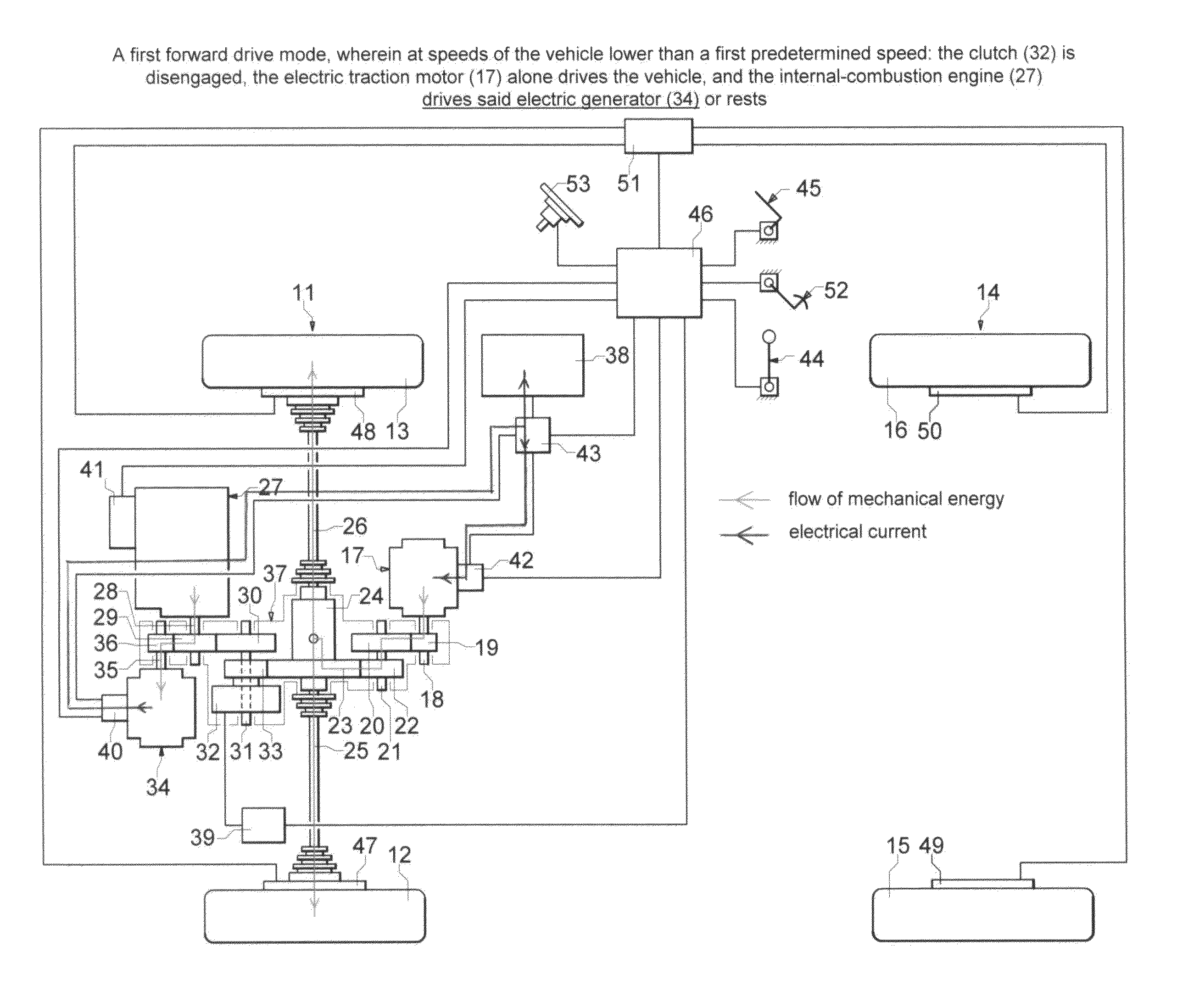
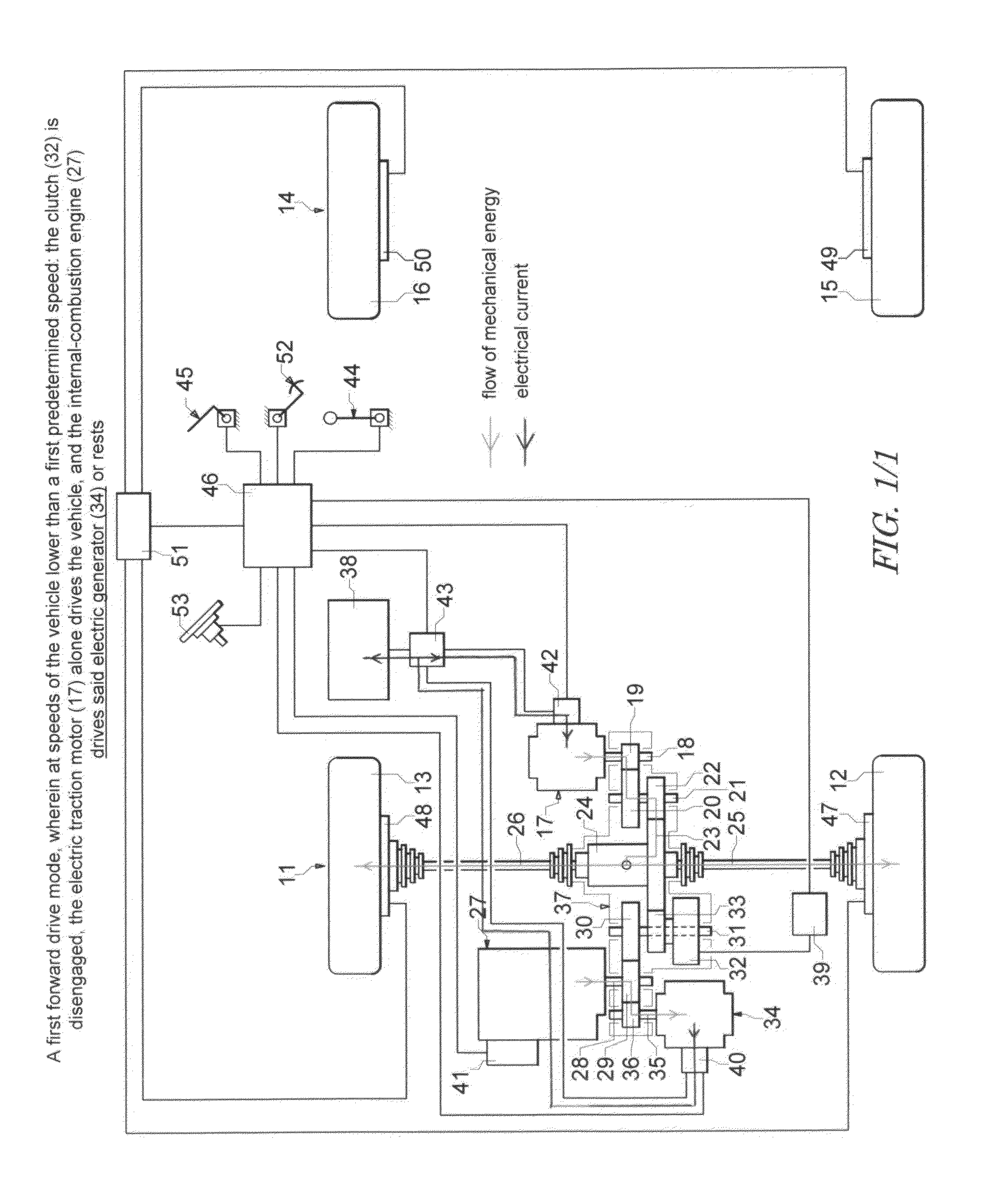
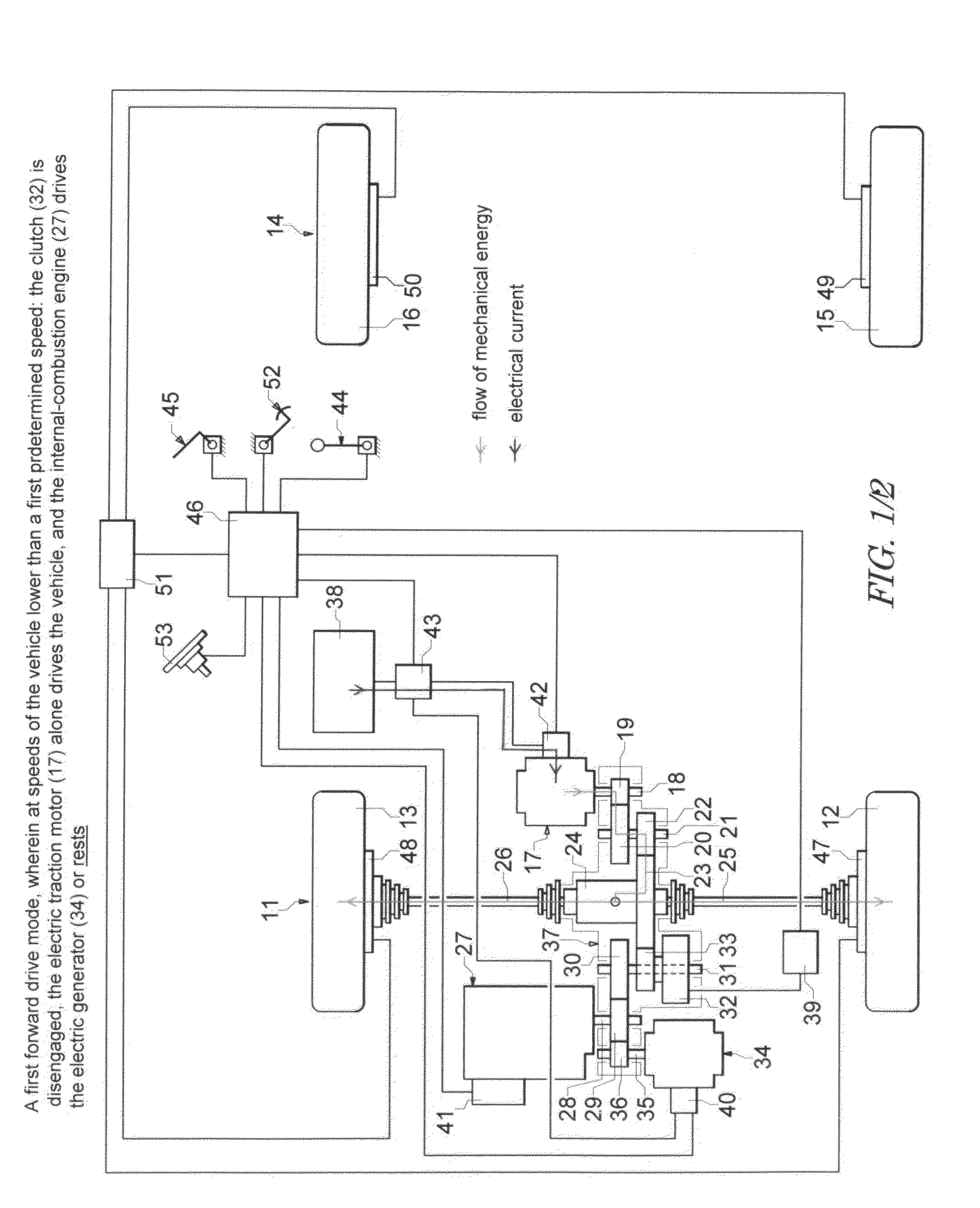
[0115]The mechanical components are shown very schematically as in views or cross sections unfolded into the plane of the drawing. The electrical components, controllers, and actuators are shown schematically as in a block diagram. The relationships between some of the components are shown with single lines regardless of how complicated these relationships might be in reality. For simplicity and clarity, no details irrelevant to the understanding of this invention are shown or described. For the same reason, some well known in the art components are mentioned but are not shown or are shown but are not described in detail. In the descriptions of the embodiments of this invention illustrated by FIG. 2 to FIG. 4, only what is different in comparison with the first embodiment illustrated by FIG. 1 is briefly described.

[0116]Referring to FIG. 1, a first axle 11 having two driving wheels 12, 13 and a second axle 14 having two free-rolling wheels 15, 16 are suspended to the frame of the ve...

third embodiment

[0173]In this third embodiment, the first mechanical drive train includes a planetary-gear type speed reducer 54. Hereinafter, for abbreviation of this description, the shorter term “planetary gear reducer” is used instead of the term “planetary-gear type speed reducer”. A sun gear 55 of the planetary gear reducer 54 is coupled with the output shaft 18 of the traction motor and is engaged with the planet gears 56 of the planetary gear reducer. A carrier 57 of the planet gears 56 is immobile. The planet gears are engaged with a ring gear 58 of the planetary gear reducer. The ring gear 58 is coupled with a clutch shaft 59. A bevel pinion gear 60 is coupled or integrated with the clutch shaft 59 and is engaged with a bevel crown gear 61 coupled with a differential 24 of the first axle 11. In this embodiment, it is assumed that the driving wheels 12, 13 are independently suspended to the frame of the vehicle and the mechanical energy is transmitted from the differential to the driving w...

fourth embodiment

[0179]In this fourth embodiment, the first mechanical drive train include said planetary gear reducer 54, as it is described with FIG. 3. Here, the clutch shaft 59 extends from the transmission enclosure 66 towards the first axle 11. A cardan shaft 67 connects the clutch shaft with an input shaft 68 of the first axle, which input shaft is coupled or integrated with said pinion gear 60. The cardan shaft 67 is actually an assembly of a shaft and two cardan joints. Such an embodiment, wherein the transmission of mechanical energy includes a cardan shaft, may be beneficial if bigger ground clearance under the traction motor is required.

[0180]In this fourth embodiment, the second mechanical drive train includes a sprocket wheel 69 coupled with the output shaft 28 of the engine 27, a clutch sprocket wheel 70 of the clutch 32, and a chain 71 engaged with said two sprocket wheels 69, 70 for transmitting mechanical energy between the engine and the clutch shaft 59. The function of the clutch...


PUM


Abstract

In a first forward drive mode, at speeds of the vehicle lower than a predetermined speed, an electric traction motor (17) drives the wheels (12, 13) of the vehicle, while an internal-combustion engine (27) drives an electric generator (34) or rests. The generator charges an electric battery (38), or powers the traction motor, or both. In a second forward drive mode, at speeds of the vehicle higher than the predetermined speed, the engine drives the electric generator and the wheels of the vehicle, while the traction motor is not energized. In a third forward drive mode, at speeds of the vehicle higher than the predetermined speed, the traction motor, powered by the electric battery, together with the engine drive the wheels of the vehicle. In a reverse drive mode the traction motor alone drives the wheels of the vehicle. A clutch (32) selectively interrupts the power transmission between the engine and the wheels of the vehicle. The traction motor selectively operates as an electric braking generator, during speed retardation and braking of the vehicle, and charges the electric battery. A central electronic controller (46) controls and coordinates the operation of the clutch, traction motor, and engine for achieving high fuel efficiency at both city and highway operational conditions.

Description

FIELD OF THE INVENTION[0001]This invention relates generally to self-propelled vehicles, and more particularly to hybrid electric vehicles.BACKGROUND OF THE INVENTION[0002]The term “hybrid electric vehicle” is usually used in the art to indicate a vehicle with a drive system including an internal-combustion engine and at least one electric traction motor. The terms “electric traction motor” is used to distinguish an electric motor utilized for vehicle propulsion from all other electric motors that may be employed in a vehicle.[0003]The sources of electric energy for the electric traction motor(s) are usually an electric generator driven by the internal-combustion engine, and an electric traction battery charged by the electric generator. In some hybrid electric vehicles, the electric traction battery is also arranged to be charged by an external source of electric energy when the vehicle is parked. The term “electric traction battery” is used to distinguish the large high-voltage el...

Claims


Application Information

Patent Timeline
Patent Type & Authority Applications(United States)
IPC IPC(8): B60W20/00B60W10/06B60K6/442B60W10/26B60W10/184B60W10/196B60W10/02B60W10/08
CPCB60W20/20B60K6/442B60W10/02B60W10/06Y10S903/93B60W10/184B60W10/196B60W10/26B60W2600/00B60W10/08B60K2006/541B60W2540/10B60W2540/12Y02T10/62
Inventor RADEV, VLADIMIR
Owner RADEV VLADIMIR
Why Eureka
Try Eureka