
Optical film and process for production the same, antireflection film and process for production the same, polarizing plate including the film, liquid crystal display device including the polarizing plate, and liquid crystal display device

a technology of anti-reflection film and production process, applied in the direction of traffic signals, roads, instruments, etc., can solve the problems of fine luminance unevenness as caused, surface shine white, glare, etc., to prevent white blurring of images, reduce reflection, and improve contrast

Active Publication Date: 2010-09-28
FUJIFILM CORP
View PDF9 Cites 10 Cited by
  • Summary
  • Abstract
  • Description
  • Claims
  • Application Information

AI Technical Summary

Benefits of technology

[0212]The amount of use of the sol component of the organosilane with respect to the fluorine-containing polymer in the low refractive index layer is preferably from 5 to 100% by weight, more preferably from 5 to 40% by weight, further preferably from 8 to 35% by weight, and especially preferably from 10 to 30% by weight. When the amount of use of the sol component is too low, the effect of the invention is hardly obtained, whereas when it is too high, the refractive index likely increases and the shape or surface properties of the film are likely deteriorated, and therefore, such is not preferable.
[0213]A variety of sol-gel raw materials can be used as a raw material for the low refractive index layer. As such a sol-gel raw material, there can be used metal alcoholate (for examples, alcoholates of silicon, titanium, aluminum, zirconium, or the like), organoalkoxy metal compounds, and hydrolyzates thereof. Above all, alkoxysilanes, organoalkoxysilanes, and hydrolyzates thereof are especially preferable. Examples thereof include tetraalkoxysilanes (for example, tetramethoxysilane and tetraethoxysilane), alkyltrialkoxysilanes (for example, methyltrimethoxysilane and ethyltrimethoxysilane), aryltrialkoxysilanes (for example, phenyltrimethoxysilane), di-alkyldialkoxysilanes, and diaryldialkoxysilanes. Also, organoalkoxysilanes having a variety of functional groups (for example, vinyltrialkoxysilanes, methylvinyldialkoxy-silanes, γ-glycidyloxypropyltrialkoxysilanes, γ-glycidyloxypropyldialkoxysilanes, β-(3,4-epoxydicyclohexyl)ethyltrialkoxysilanes, γ-methacryloyloxypropyltrialkoxysilanes, γ-aminopropyltrialkoxysilanes, γ-mercaptopropyltrialkoxysilanes, and γ-chloropropyltrialkoxysilanes), perfluoroalkyl group-containing silane compounds (for example, (hepta-decafluoro-1,1,2,2-tetradecyl)triethoxysilane and 3,3,3-trifluoropropyltrimethoxysilane) are preferably used. Use of a fluorine-containing silane compound is especially preferable in view of realizing a low refractive index of the layer and imparting water repellency or oil repellency.(Other Substance to be Contained in the Composition for Low Refractive Index Layer)
[0214]In addition to the foregoing fluorine-containing polymer, inorganic fine particle and organosilane compound, a variety of additives and a radical polymerization initiator or a cationic polymerization initiator can be added in the composition for low refractive index layer as the need arises. On that occasion, though the concentration of solids such as additives is properly selected depending upon the application, it is generally from about 0.01 to 60% by weight, preferably from about 0.5 to 50% by weight, and especially preferably from about 1 to 20% by weight.
[0215]From the viewpoints of interfacial adhesiveness between the low refractive index layer and a lower layer coming into direct contact therewith and so on, a small amount of a hardening agent such as polyfunctional (meth)acrylate compounds, polyfunctional epoxy compounds, polyisocyanate compounds, aminoplasts, and polybasic acids or anhydride thereof can be added. In the case of adding such a hardening agent, it is preferably added in an amount in the range of not more than 30% by weight, more preferably in the range of not more than 20% by weight, and especially preferably in the range of not more than 10% by weight based on the whole of solids of the low refractive index layer film.
[0216]Furthermore, for the purpose of imparting characteristics such as antifouling properties, water-proof properties, chemical resistance, and slipperiness, known antifouling agents and slipping agents made of a silicone based compound or a fluorine based compound and so on can be properly added. In the case where such an additive is added, the amount of addition of the additive is preferably in the range of from 0.01 to 20% by weight, more preferably in the range of from 0.05 to 10% by weight, and especially preferably in the range of from 0.1 to 5% by weight of the whole of solids of the low refractive index layer.
[0217]Preferred examples of the silicone based compound include compounds containing plural dimethylsilyloxy units as a repeating unit and containing a substituent in a terminal and / or a side chain of the chemical chain thereof Furthermore, a structural unit other than dimethylsilyloxy may be contained in the chemical chain containing dimethylsilyloxy as a repeating unit. The substituent may be the same or different, and it is preferable that plural substituents are contained. Preferred examples of the substituent include groups containing, for example, an acryloyl group, a methacryloyl group, a vinyl group, an aryl group, a cinnamoyl group, an oxetanyl group, a fluoroalkyl group, a polyoxyalkylene group, a carboxyl group, or an amino group. Though the molecular weight of this polysiloxane based compound is not particularly limited, it is preferably not more than 100,000, more preferably not more than 50,000, especially preferably from 3,000 to 30,000, and most preferably from 10,000 to 20,000. Though the silicon atom content of the silicone based compound is not particularly limited, it is preferably 18.0% by weight or more, especially preferably from 25.0 to 37.0% by weight, and most preferably from 30.0 to 37.0% by weight. Preferred examples of the silicone based compound include X-22-174DX, X-22-2426, X-22-164B, X-22-164C, and X-22-1821 (all of which are a trade name of Shin-Etsu Chemical Co., Ltd.); FM-0725, FM-7725, FM-6621, and FM-1121 (all of which are a trade name of Chisso Corporation); and DMS-U22, RMS-033, RMS-083, UMS-182, DMS-H21, DMS-H31, HMS-301, FMS121, FMS123, FMS131, FMS141, and FMS221 (all of which are a trade name of Gelest, Inc.).

Problems solved by technology

In particular, in the case where an antireflection film having strong antiglare properties for the purpose of reducing the reflection, in recent years, following the progress of high definition of display devices, fine luminance unevenness as caused due to surface irregularities of the antireflection film (named as “glare”) has become problematic.
In the case where a conventional film having an antiglare layer is applied on the surface of a display device, it has become problematic that the surface shines whitely as a whole in a bright room (hereinafter referred to as “white blurring”).
However, since there is caused a problem that the high internal scattering properties lower the contrast which a display device originally possesses, the antiglare film is not always optimum to this application.
However, U.S. Publication 2001 / 043302 (corresponding to Japanese Patent 3602438) does not describe the front contrast and the contrast in an oblique direction of the display device.
Furthermore, U.S. Publication 2001 / 043302 (corresponding to Japanese Patent 3602438) does not describes the surface reflectance and the surface haze of the film, is not sufficient with respect to classification between an internal haze and a surface haze, and does not sufficiently describe improvements in an image display performance in a bright room.

Method used

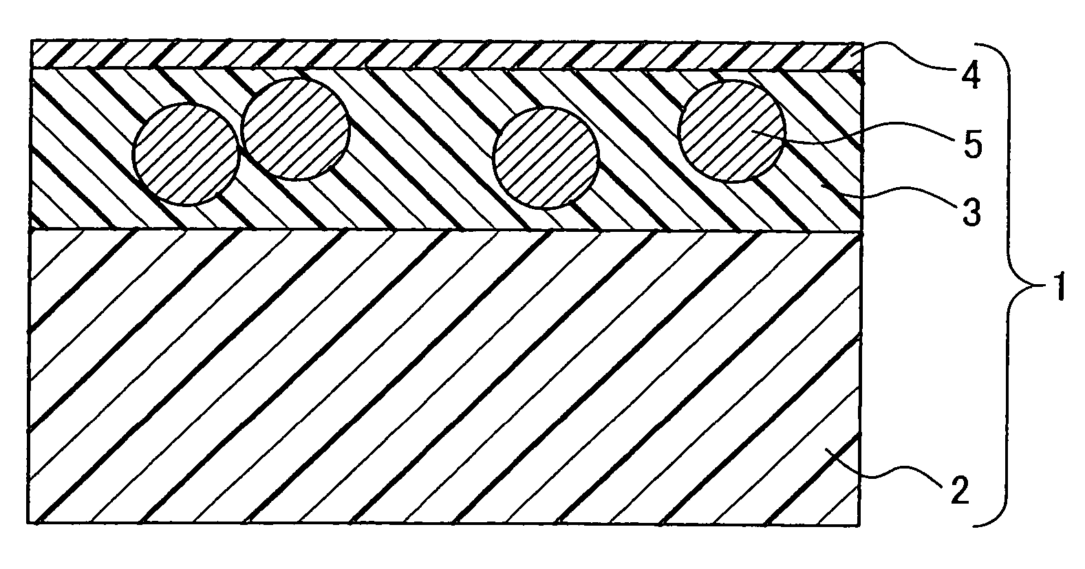
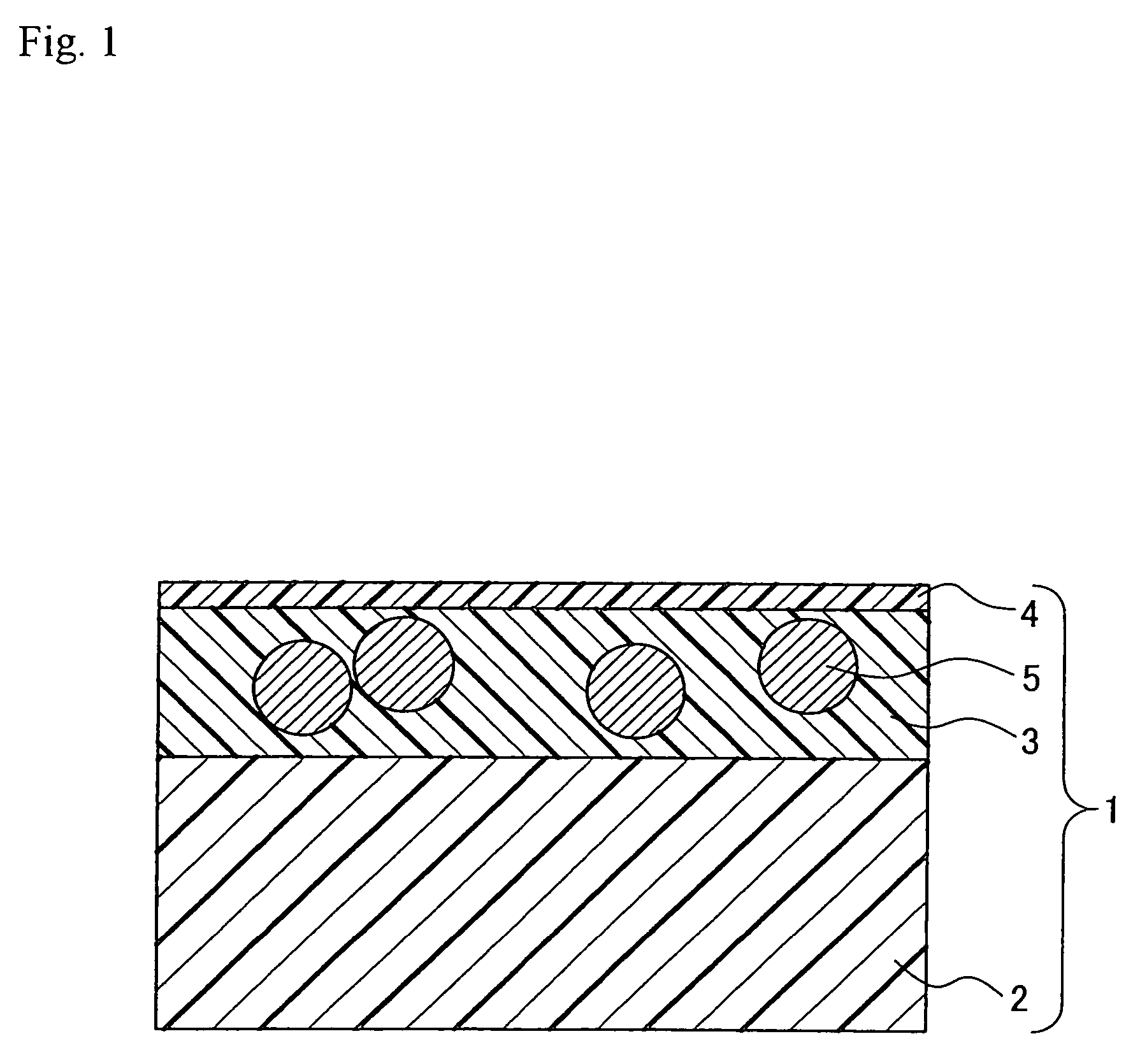

Image

  • Optical film and process for production the same, antireflection film and process for production the same, polarizing plate including the film, liquid crystal display device including the polarizing plate, and liquid crystal display device
  • Optical film and process for production the same, antireflection film and process for production the same, polarizing plate including the film, liquid crystal display device including the polarizing plate, and liquid crystal display device
  • Optical film and process for production the same, antireflection film and process for production the same, polarizing plate including the film, liquid crystal display device including the polarizing plate, and liquid crystal display device

Examples


example 1

(Preparation of Coating Solution A for Internal Scattering Layer)

[0332]71.0 g of a mixture of pentaerythritol triacrylate and pentaerythritol tetraacrylate (PET-30, manufactured by Nippon Kayaku Co., Ltd.), 3.0 g of a polymerization initiator (IRGACURE 184, manufactured by Ciba Speciality Chemicals), 0.1 g of a fluorine based surface modifier (EP-149), and 11.9 g of a silane coupling agent (KBK-5103, manufactured by Shin-Etsu Chemical Co., Ltd.) were added in a mixed solvent of methyl isobutyl ketone and methyl ethyl ketone, and the mixture was stirred for 60 minutes by an air dispersion device, thereby completely dissolving the solutes. A coating film obtained by coating this solution and hardening by ultraviolet rays had a refractive index of 1.520. 6.3 g of a crosslinked poly(styrene) polymer having an average particle size of 3.5 μm (refractive index: 1.600) and 7.7 g of a crosslinked poly(acryl-styrene) particle having an average particle size of 3.5 μm (copolymerization compos...

example 2

[0381]An 80 μm-thick triacetyl cellulose film (TAC-TD80U, manufactured by Fuji Photo Film Co., Ltd.) which had been dipped in an NaOH aqueous solution of 1.5 moles / L at 55° C. for 2 minutes, neutralized and then washed with water and each of the saponified antireflection films as prepared in Example 1 (Examples 1-1 to 1-14 and Comparative Examples 1-1 to 1-10) were made to adhere for protection to the both surfaces of a polarizer as prepared by adsorbing iodine on polyvinyl alcohol and stretching, thereby preparing a polarizing plate. The thus prepared polarizing plates were designated as Examples 2-1 to 2-14 and Comparative Examples 2-1 to 2-10.

[0382]Furthermore, a polarizing plate was prepared by using the foregoing saponified triacetyl cellulose film as a protective film of the both surfaces and was designated as Comparative Example 2-11.

example 3

(Evaluation of Polarizing Plate)

[0383]Each of the polarizing plates of Examples 2-1 to 2-14 and Comparative Examples 2-1 to 2-11 as prepared in Example 2 was stuck in place of a polarizing plate in a viewing side of a liquid crystal television set. As the liquid crystal television set, “LC-37GD4” (MVA mode) as manufactured by Sharp Corporation was used.

[0384]The resulting display devices were evaluated with respect to the following items. The results are shown in Table 4.

(1) White Blurring:

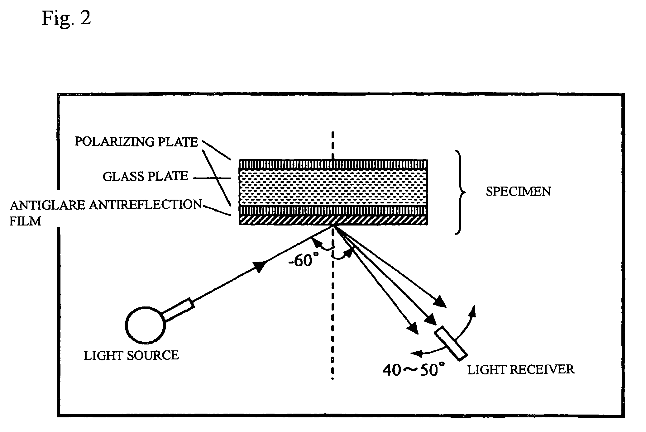
[0385]With respect to an LCD television panel (VA mode) having a definition and an image size as shown in the table, a polarizing plate of the surface side was replaced by the polarizing plate of this Example; the entire surface was displayed black; a naked fluorescent lamp (8,000 cd / m2) not provided with a louver was reflected from the upper direction at an angle of 60° in a dark room; and in the visual observation from the front, the white light state (white blurring) of the entire face was eval...


PUM

PropertyMeasurementUnit
thicknessaaaaaaaaaa
particle sizeaaaaaaaaaa
refractive indexaaaaaaaaaa

Abstract

An optical film comprising a transparent support and a layer having internal scattering properties, wherein the optical film has an image sharpness, as measured in an optical comb width of 0.5 mm in conformity to JIS K7105, of from 30.0% to 99.9%, a haze value as caused by surface scattering of less than 3%, and a haze value as caused by internal scattering of from 15 to 40%.

Description

FIELD OF THE INVENTION[0001]The present invention relates to an optical film, to an antireflection film (one example of an optical film), to a polarizing plate and to an image display device. In more detail, the invention relates to an antireflection film having a layer having internal scattering properties and a low refractive index layer, which is substantially free from white blurring in a bright room and is good in contrast in a bright room and which when used for the surface of a liquid display device, is able to improve the contrast in an oblique direction without reducing the front contrast; to a polarizing plate including the antireflection film as a surface protective film; and to an image display device including the antireflection film polarizing plate.BACKGROUND OF THE INVENTION[0002]In general, in display devices such as CRT, a plasma display (PDP), an electroluminescence display (ELD), and a liquid crystal display device (LCD), for the purpose of preventing reflection ...

Claims


Application Information

Patent Timeline
Patent Type & Authority Patents(United States)
IPC IPC(8): B32B3/00G02B27/00
CPCG02B1/111G02F1/133502Y10T428/24372Y10T428/24355Y10T428/24405G02F1/13363
Inventor INOUE, KATSUMIASAKURA, TETSUYA
Owner FUJIFILM CORP
Learn More