

Electromagnetic wrap
a technology of electromagnetic wrap and insulating conductor, which is applied in the direction of insulated conductors, rigid-tube cables, cables, etc., can solve the problems of current surges, system incapacitation, and insulation breaking in the system
- Summary
- Abstract
- Description
- Claims
- Application Information
AI Technical Summary
Problems solved by technology
Method used
Image

Examples
Embodiment Construction
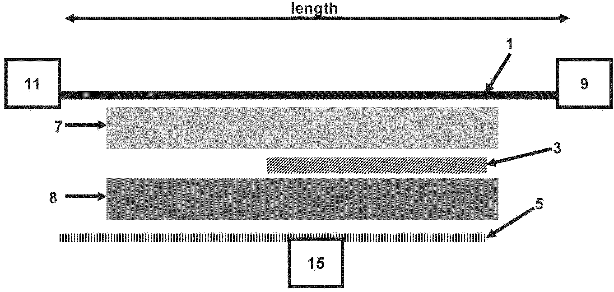
[0026]An electromagnetic wrap device and method for altering the line reactance (combination of capacitance, inductance, and resistivity) of a transmission line having a transmission line, a first floating conductor and a grounding conductor. The first floating conductor is positioned at least partially between and electrically insulated from the transmission line and the grounding conductor. A source and a load are connected at opposite ends of the transmission line.
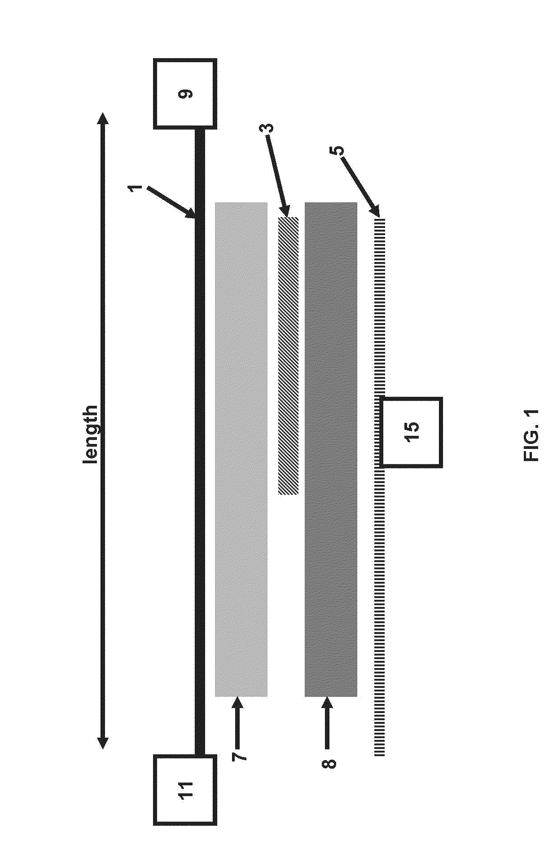
FIG. 1
[0027]FIG. 1 depicts a longitudinal cross section view of one embodiment of an electromagnetic wrap having a transmission line 1, a first floating conductor 3, and a grounding conductor 5. The first floating conductor 3 is positioned between the transmission line 1 and the grounding conductor 5. In the embodiment shown in FIG. 1 the first floating conductor 3 runs at least partially along the length of the transmission line 1. A first insulator 7 electrically insulates the transmission line 1 from the first floati...
PUM
| Property | Measurement | Unit |
|---|---|---|
| frequency | aaaaa | aaaaa |
| length | aaaaa | aaaaa |
| length | aaaaa | aaaaa |
Abstract
Description
Claims
Application Information