

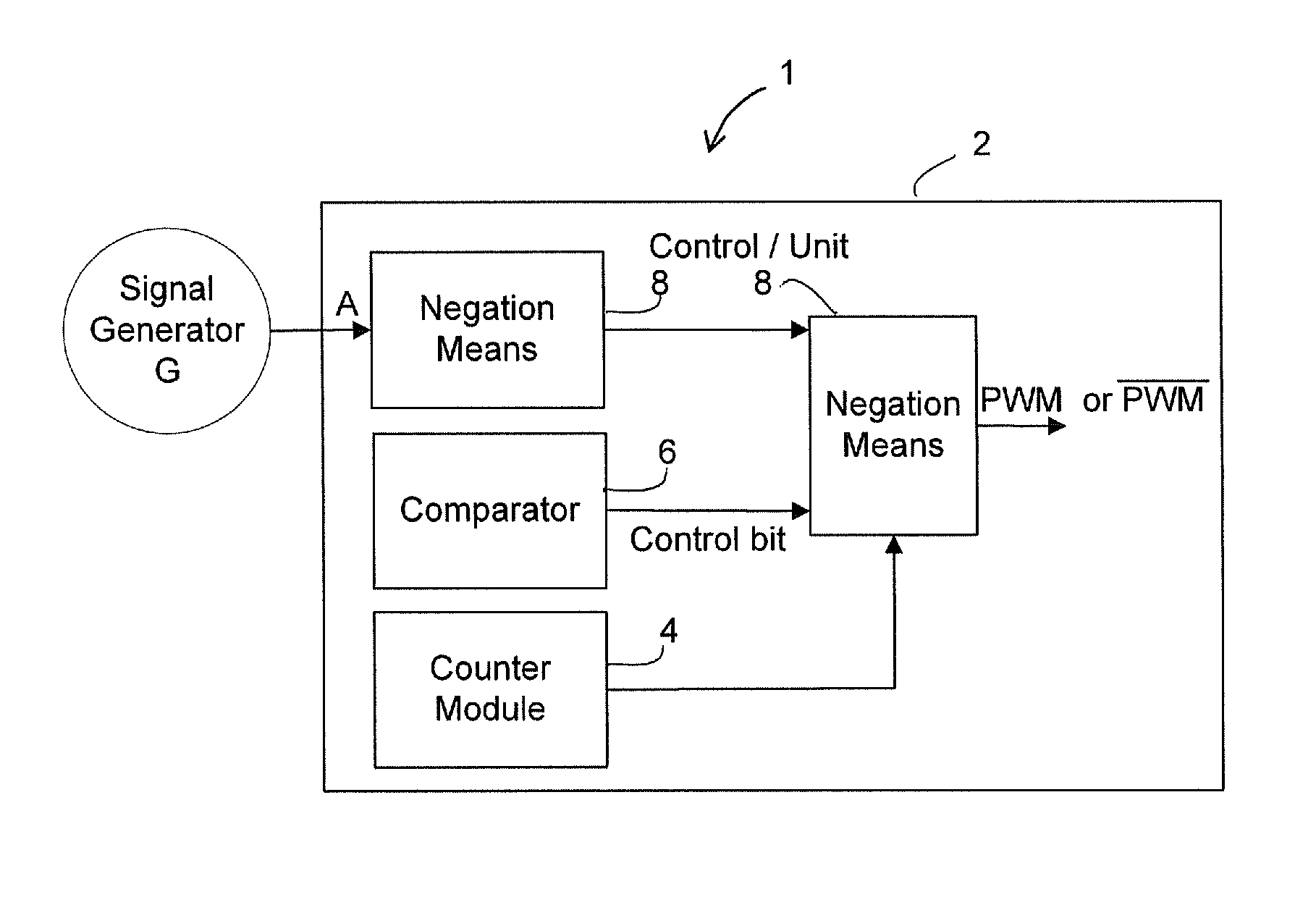
Method and apparatus for pulse width modulation
a pulse width and modulation technology, applied in the field of pulse width modulation methods and apparatuses, can solve the problems of affecting the detection error-free measurement of electrical and non-electrical measurement variables without restricting the modulation range is possible only with increased complexity, and achieves the effect of reliable keeping free of switching times
- Summary
- Abstract
- Description
- Claims
- Application Information
AI Technical Summary
Benefits of technology
Problems solved by technology
Method used
Image

Examples
Embodiment Construction
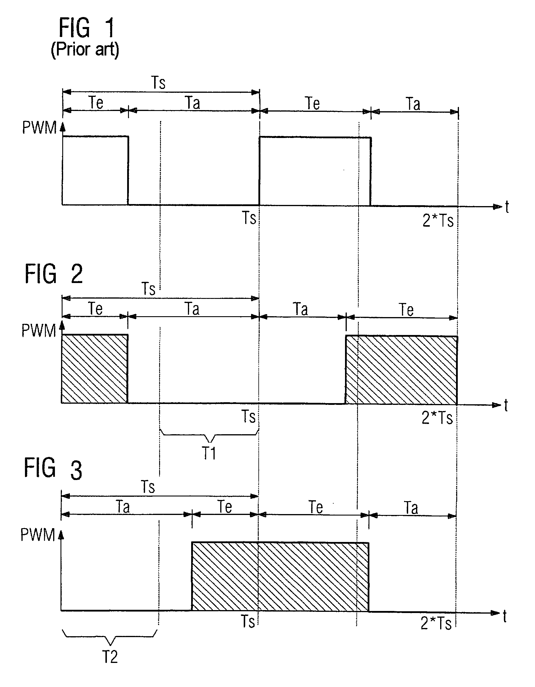
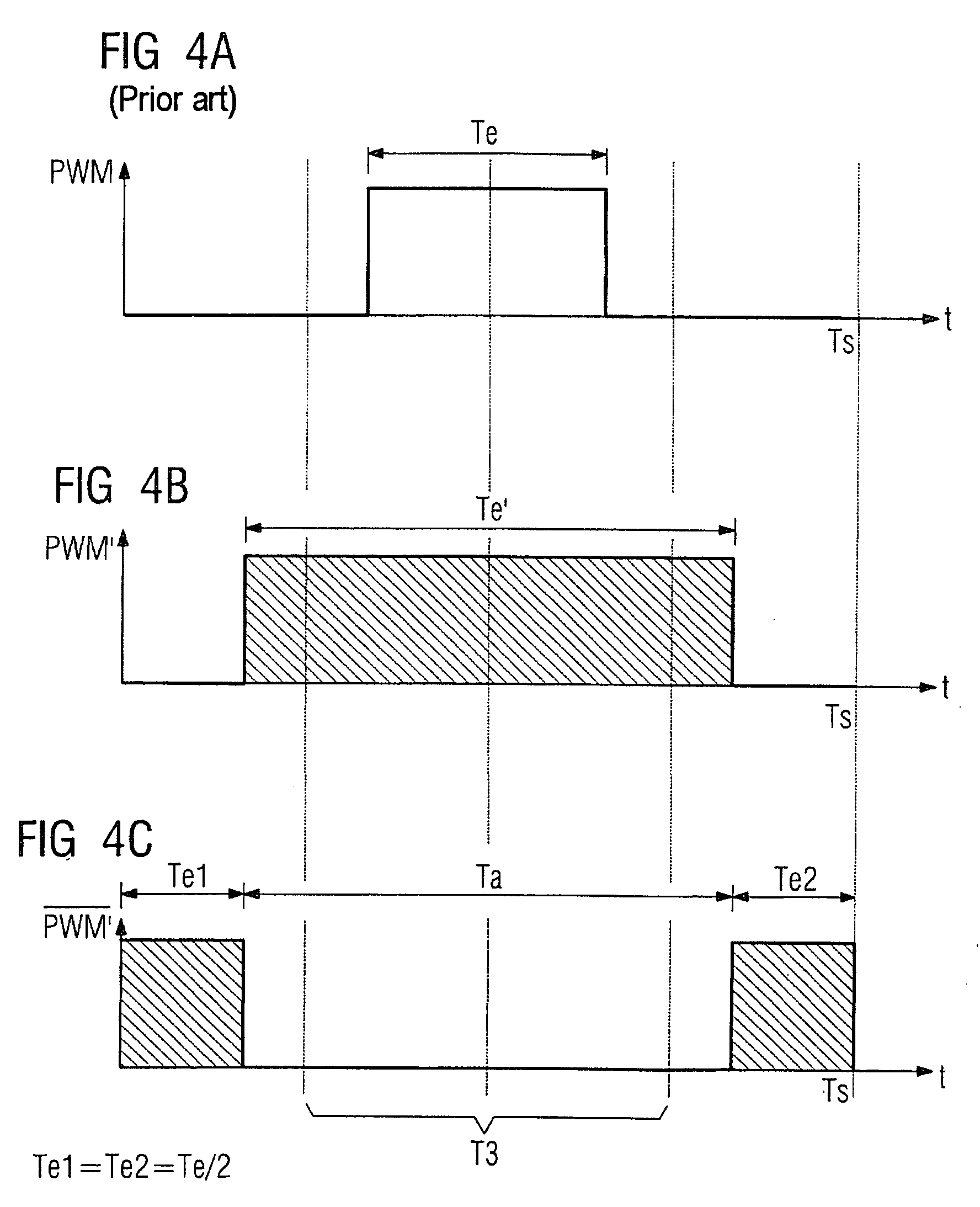
[0024]FIG. 1 shows a timing diagram of a discrete sequence of switch-on operations with a switch-on duration Te and switch-off operations with a switch-off duration Ta of a pulse-width-modulated signal PWM in the prior art. The pulse width modulation method on which the timing diagram is based has a predefined switching period Ts. In this case, the pulse width modulation is used to generate the sequence of switch-on operations and switch-off operations with a variable ratio of the switch-on duration Te to the switch-off duration Ta within the switching period Ts. Such a conventional pulse width modulation method is used, for example, in power electronics to drive electrical machines or devices and systems pertaining to consumer electronics.
[0025]In order to detect electrical and non-electrical measurement variables at the device to be controlled, for example a DC chopper controller, in a manner that is largely free of the switching operations of the pulse width modulation method, th...
PUM
 Abstract
Description
Claims
Application Information