Valve-integrated transponder
a transponder and valve technology, applied in the direction of burglar alarm mechanical actuation, instruments, transportation and packaging, etc., can solve the problems of increasing the size of the casing, affecting the operation of the vehicle, and inevitably needing a complicated process, so as to increase the field intensity of radio waves, prevent damage, and enhance mechanical strength
- Summary
- Abstract
- Description
- Claims
- Application Information
AI Technical Summary
Benefits of technology
Problems solved by technology
Method used
Image
Examples
first embodiment
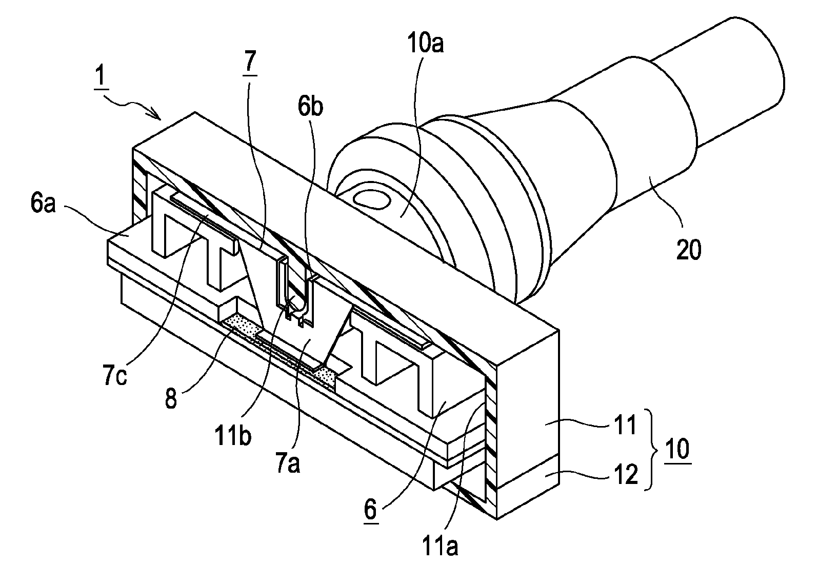
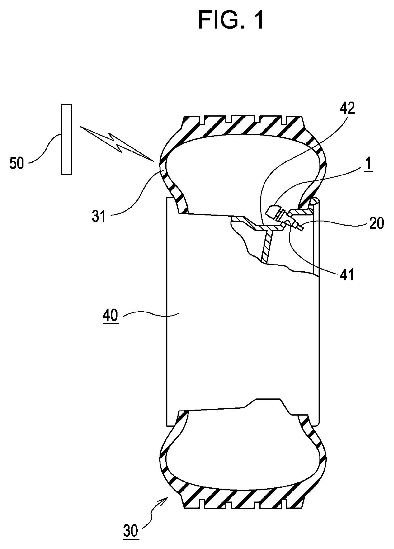
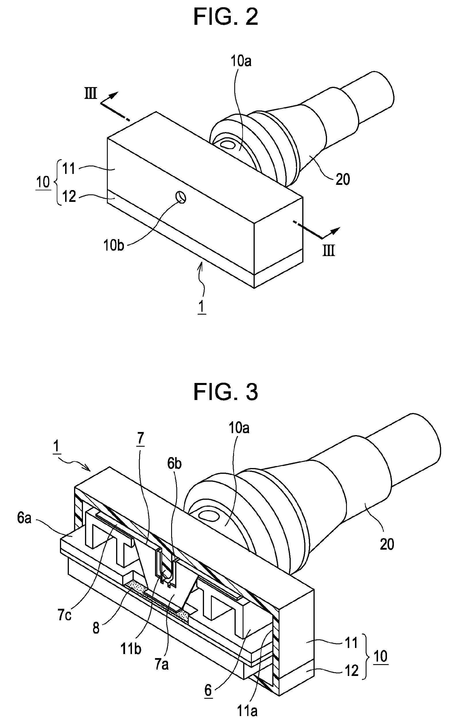
[0020]Embodiments of the present invention will now be described with reference to the drawings. FIG. 1 illustrates a mounting position of a valve-integrated transponder according to the present invention inside a tire. FIG. 2 is an external view of the transponder and an air valve. FIG. 3 is a cross-sectional view taken along line III-III in FIG. 2. FIG. 4 illustrates the internal structure of the transponder as viewed from an external-antenna side. FIG. 5 illustrates the internal structure of the transponder as viewed from an air-valve side.
[0021]A valve-integrated transponder 1 shown in these drawings is fitted to one end of a snap-in type air valve 20 and disposed within a tire 30, and is for enabling a driver at the driver seat to monitor the air pressure and temperature inside the tire 30. The transponder 1 has a synthetic-resin casing 10 that houses a detection circuit unit 2 having detecting elements such as a pressure sensor and a temperature sensor, a transmitter / receiver ...
second embodiment
[0031]FIG. 6 illustrates the internal structure of a valve-integrated transponder according to the present invention as viewed from an external-antenna side. FIG. 7 illustrates the internal structure of the transponder as viewed from an air-valve side. The components shown in FIGS. 6 and 7 that correspond to those in FIGS. 4 and 5 are indicated with the same reference numerals, and descriptions of those components will not be repeated.
[0032]The second embodiment differs from the first embodiment in the shape of the feed terminal 7b of the antenna element 7. Specifically, referring to FIGS. 6 and 7, the feed terminal 7b has a U-shaped segment 7d and is disposed along a side surface of the central erected portion 6c of the supporting member 6, the side surface being opposite to that provided with the ground terminal 7a. Opposite ends of the U-shaped segment 7d are continuously connected to the pair of radiation conductors 7c that are arranged side by side with the recessed slot 6b the...
PUM
 Abstract
Description
Claims
Application Information
 - R&D
- Intellectual Property
- Life Sciences
- Materials
- Tech Scout
- Unparalleled Data Quality
- Higher Quality Content
- 60% Fewer Hallucinations
Browse by: Latest US Patents, China's latest patents, Technical Efficacy Thesaurus, Application Domain, Technology Topic, Popular Technical Reports.
© 2025 PatSnap. All rights reserved.Legal|Privacy policy|Modern Slavery Act Transparency Statement|Sitemap|About US| Contact US: help@patsnap.com


