System and method for the guidance of a catheter in electrophysiologic interventions

a catheter and electrophysiologic technology, applied in the field of interventional systems and methods for cardiovascular interventions with catheters, can solve the problems of long procedure time, difficult and lengthy procedure, and the catheter is not able to reach the desired ep signal location, so as to achieve optimal accuracy and reduce the effect of movement and/or deformation of the interventional region due to heart bea

Active Publication Date: 2010-09-28
KONINKLIJKE PHILIPS ELECTRONICS NV
View PDF12 Cites 48 Cited by
  • Summary
  • Abstract
  • Description
  • Claims
  • Application Information

AI Technical Summary

Benefits of technology

[0015]An interventional system of the aforementioned kind is very helpful for the navigation of a catheter during electrophysiological procedures, because the determination of the target position on a live image helps to guide the catheter to the desired tissue showing a characteristic electrographic pattern. It is no longer necessary to find said tissue in a lengthy iterative procedure of advancing the catheter stepwise while comparing the recorded electrographic signals with the desired ones. Thus the duration of the intervention can be reduced, which means less stress and X-ray exposure for the patient and the medical personnel.
[0019]The localization of the catheter (or its electrode) and / or of the reference instrument (if present) on the reference image can be facilitated if it is identified on one image of the images of the sequence and then tracked in the other images of the sequence. The localization on any image may thus be based on the already know locations on the (with respect to the temporal order of the image sequence) previous / following image. The identification of the catheter or the reference instrument on a first image may be interactively achieved with the help of a user. The human interaction is particularly helpful for distinguishing the (interventional) catheter from a reference catheter, because they both may look identical or very similar to each other on the images. In this case the identification provided by the user can be propagated to all images by the mentioned tracking.
[0020]In a further development of the investigation system, a reference image is selected that corresponds to the same heart phase as the actual image (while of course simultaneously belonging to the desired electrophysiological pattern). The heart phase that corresponds to an image can readily be determined because electrographic signals are recorded parallel to the image generation. By the selection of an image with a similar heart phase as the actual image, movements and / or deformations of the interventional region due to heart beat can be reduced a minimum.
[0021]The system may furthermore be adapted to compensate the effect that respiration motion has on the catheter and / or on a reference instrument in the sequence of images and in the actual image. Respiration motion may particularly be compensated based on the a-priorily extracted motion of catheter positions due to respiration and a continuous determination of the depth of respiration from acquired images or external respiration sensors.
[0022]To achieve an optimal accuracy, the aforementioned approaches are preferably combined. Thus the system can display the position of a (reference) catheter after compensation of heart beat and respiration motion, wherein heart beat motion is compensated by continuously updating the selection of the reference image such that it corresponds to the heart phase of the actual image, which is identified by the synchronously acquired ECG. The compensation of both kinds of motions is particularly important for the accurate navigation and repositioning of a catheter at a previously determined position.

Problems solved by technology

These procedures require a long time with a typical duration of several hours and an associated large patient X-ray dose.
The presence of arrhythmogenic tissue or abnormal pathways bypassing the normal conducting fibers can cause tachycardias.
The navigation of the catheter to the location with a desired EP signal remains however a rather difficult and lengthy procedure.

Method used


Image

  • System and method for the guidance of a catheter in electrophysiologic interventions
  • System and method for the guidance of a catheter in electrophysiologic interventions

Examples


Embodiment Construction

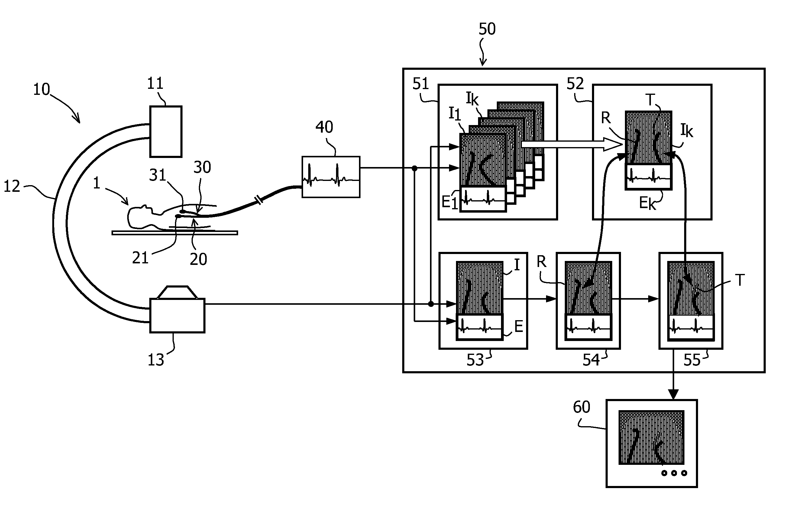
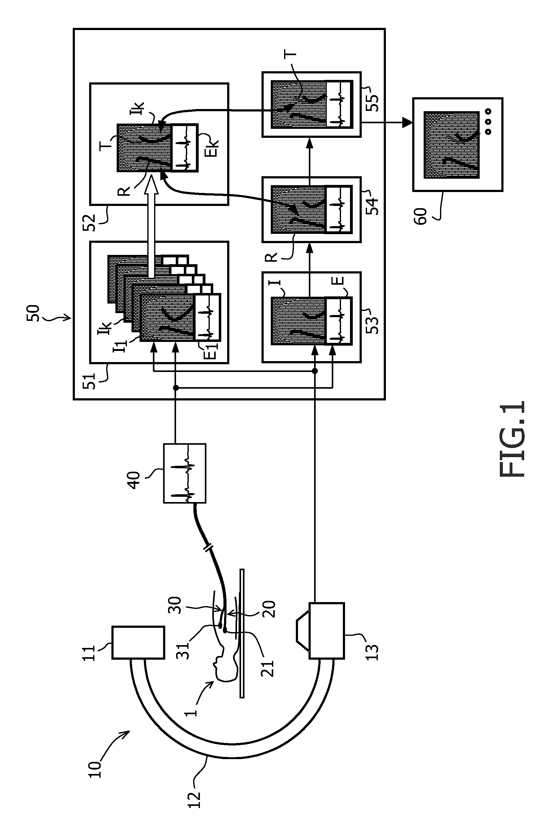
[0034]On the left side of the FIGURE, a rotational X-ray device 10 is depicted that consists of an X-ray tube 13 and an X-ray detector 11 which are connected by a C-arm 12. The X-ray device 10 allows the generation of X-ray projections from different directions of a patient 1 lying on a table in the centre of the device. Instead of an X-ray device, other imaging devices could be used as well.

[0035]The FIGURE further shows a catheter 20 that is advanced through the vessel system of the patient 1 into the heart. An electrode 21 at the tip of the catheter is coupled to an electrocardiographic device 40 for recording electrophysiological potentials of the tissue contacting the electrode 21. For the electrophysiological measurements, a second or “reference” catheter 30 is present and connected to the electrographic device 40, too, wherein said catheter 30 and its reference electrode 31 usually rest at a constant anatomical position during the whole intervention.

[0036]A typical applicatio...


PUM


Abstract

In a system and a method for the guidance of a catheter with an electrode in an electrophysiological procedure, sequence of images of the catheter and of a resting reference catheter is generated with an X-ray device and stored together with the associated electrographic recordings from the electrodes. A reference image may then be selected from said sequence that corresponds to a desired electrographic pattern. In a next step, the positions of the catheters are localized on the reference image. The position of the reference catheter can be identified with the position of this catheter on an actual image. Thus it is possible to determine on the actual image also a target position for the catheter that corresponds to the position of this catheter on the reference image. The target position may finally be indicated on a monitor to assist the guidance of the catheter to a desired location.

Description

FIELD OF THE INVENTION[0001]The invention relates to an interventional system and a method for cardiovascular interventions with a catheter that records electrophysiological signals.BACKGROUND OF THE INVENTION[0002]There are increasingly more electrophysiological (EP) procedures carried out on cardiovascular X-ray systems. These procedures require a long time with a typical duration of several hours and an associated large patient X-ray dose. It is, therefore, important to provide functionality to the X-ray system which facilitates system usage, shortens the time for performing the procedure, and reduces X-ray dose.[0003]One particular example of an EP procedure is the minimally invasive treatment of tachycardias, i.e. abnormally rapid rhythms of the heart. Multiple fibers run through the heart muscles that are responsible for the propagation of electrophysiological signals. The presence of arrhythmogenic tissue or abnormal pathways bypassing the normal conducting fibers can cause t...

Claims


Application Information

Patent Timeline
Patent Type & Authority Patents(United States)
IPC IPC(8): A61B5/05A61B6/00A61B5/04A61N1/00
CPCA61B5/042A61B5/06A61B6/12A61B6/4441A61B6/487A61B6/503A61B6/5288A61B5/283
Inventor WEESE, JUERGENMOLLUS, SABINEECK, KAIBREDNO, JOERG
Owner KONINKLIJKE PHILIPS ELECTRONICS NV
Why Eureka
Try Eureka