
Spindle lock for a hand-held combination drill and chisel hammer

a combination drill and pin lock technology, which is applied in the direction of turning apparatus, portable percussive tools, bulkheads/piles, etc., can solve the problems of high manufacturing and assembly costs, complex mounting steps, and difficulty in accurately assembling guide pins taking into account the required strength, so as to improve functional safety and reduce manufacturing and assembly costs

Active Publication Date: 2010-10-05
AEG ELECTRIC TOOLS
View PDF24 Cites 13 Cited by
  • Summary
  • Abstract
  • Description
  • Claims
  • Application Information

AI Technical Summary

Benefits of technology

[0006]It is an object of the present invention to develop a spindle lock of the aforementioned kind in such a way that the manufacturing and assembly expenditure is reduced while at the same time the functional safety is improved.
[0008]The integral (monolithic) formation of the guide rail arrangement part on the gearbox housing eliminates the need for a separate attachment of a guide pin. The manufacturing and assembly expenditure is reduced and at the same time the positional precision is improved. The integration of the guide rail arrangement into the gearbox housing increases the load-bearing capacity. The extension of the guide rail arrangement parallel to the displacement direction avoids any canting of the locking plate and improves its guiding precision. As a whole, the operational safety of the spindle lock is improved.
[0009]In a preferred embodiment, the guide rail arrangement comprises at least one and preferably two guide slots extending parallel to the axis of rotation in which guide slots a gliding surface is slidably guided, respectively. For a minimal surface pressure and thus minimal component load a high guiding precision and safety with regard to canting safety are provided. The gliding surfaces can be threaded during assembly with minimal expenditure into the assigned guide slots so that assembly expenditure is reduced. When providing several guide slots, the guide slots are advantageously arranged angularly to one another and in particular at a right angle relative to one another. In this way, a fixation of the locking plate in all spatial degrees of freedom with the exception of the displacement direction is possible. Already upon threading of the locking plate into the guide rail arrangement, a suitable positional orientation is provided; this further reduces the assembly expenditure. In the completed mounted state the guiding precision is further improved.
[0010]It can be expedient to provide one or several guide slots in the locking plate while suitable projections of the gearbox housing engage as gliding surfaces these guide slots. Preferably, the reverse embodiment is selected in which the guide slots are formed in the gearbox housing and the correlated gliding surface is formed by the locking plate. The geometrically complex guide slots can be formed without problems in an injection mold or a die-casting mold of the gearbox housing. In regard to the locking plate, it is sufficient to provide the required gliding surfaces by means of simple reshaping measures. Accordingly, the manufacturing expenditure is thus reduced.
[0011]In a preferred embodiment, a normal to the gliding surface extends parallel to the direction of width of the associated guide slot. Under operating load, the gliding surface is thus loaded only perpendicularly to the surface while ribs or other suitable shapes of the gearbox housing in which the respective guide slot is formed, respectively, are loaded only in their plane while transverse forces are avoided. The arrangement can therefore be of a thin-wall construction and lightweight.
[0012]In an advantageous embodiment, the guide means comprise a guide pin configured as an integral part of the gearbox housing which guide pin engages a guide opening of the locking plate. By means of the integral configuration of the guide pin and the gearbox housing, a separate mounting step for the guide pin as an individual part is not required. The guide pin contributes to a spacial positional alignment of the locking plate and thus further improves the guiding action for the locking plate provided by the guide rail arrangement. The pin shape enables moreover a double function according to which the guide pin secures and positionally fixes a spring that is embodied in particular as a pressure coil spring. This spring is provided for an automatic axial displacement of the locking plate.

Problems solved by technology

A precise assembly of the guide pins taking into account the required strength is difficult and complex.
This mounting step is also complex and costly because the guide plate must be secured in position against the pretension force of the spring until additional assemblies that are subsequently mounted take over this securing or fixation function.

Method used


Image

  • Spindle lock for a hand-held combination drill and chisel hammer
  • Spindle lock for a hand-held combination drill and chisel hammer
  • Spindle lock for a hand-held combination drill and chisel hammer

Examples


Embodiment Construction

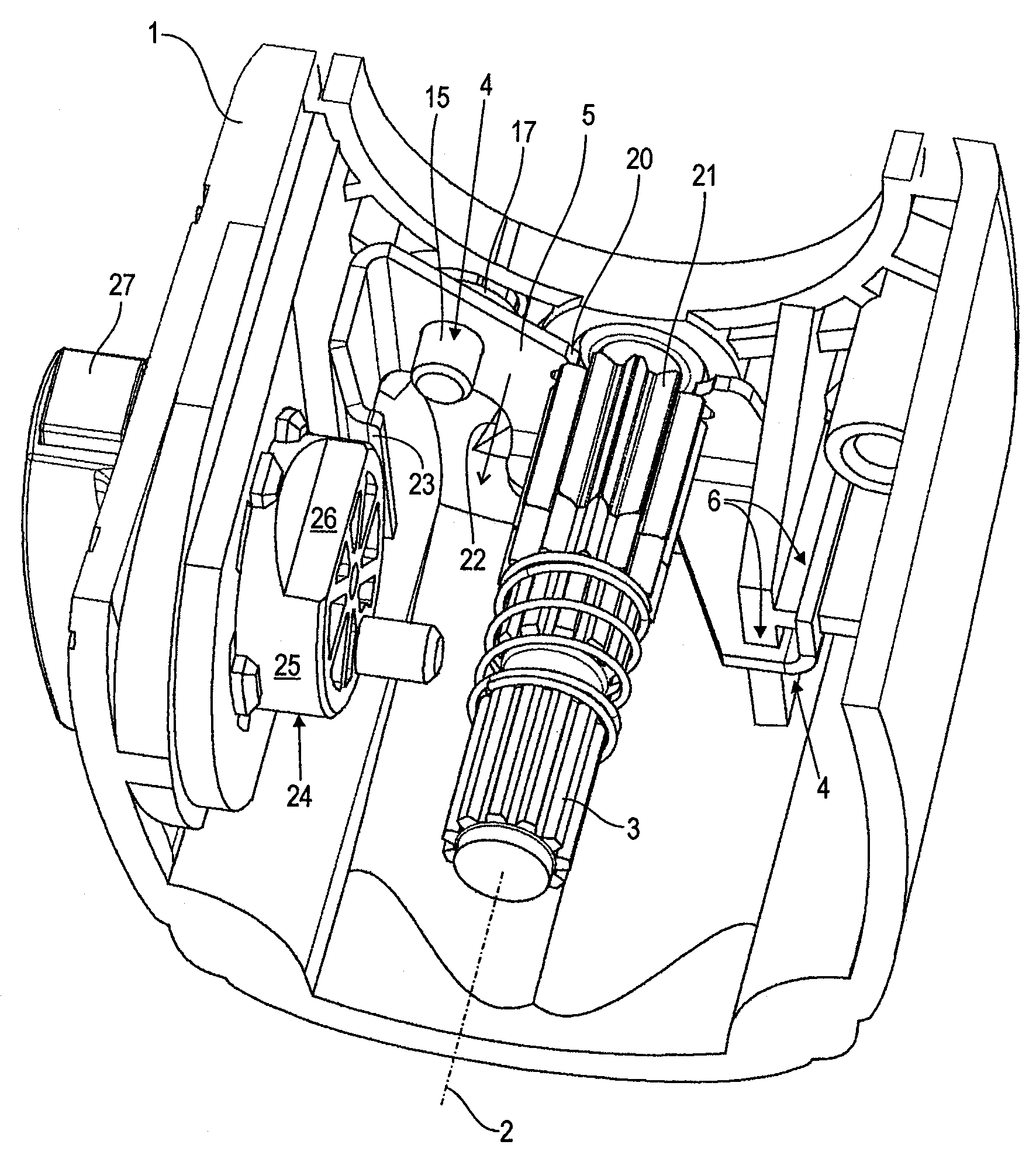
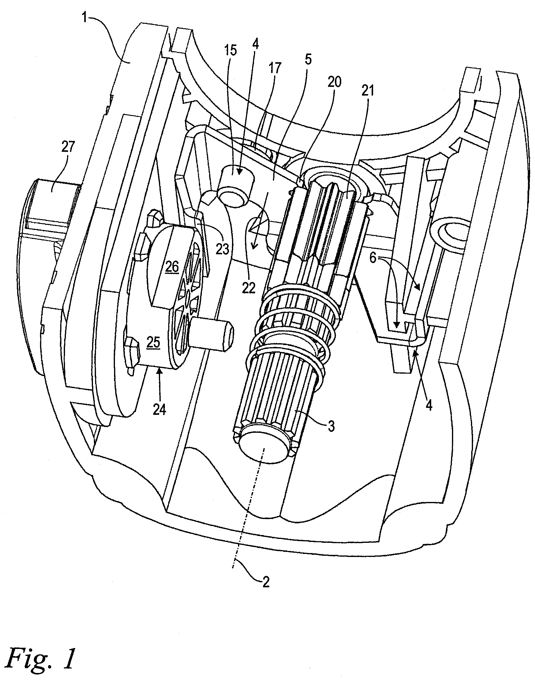
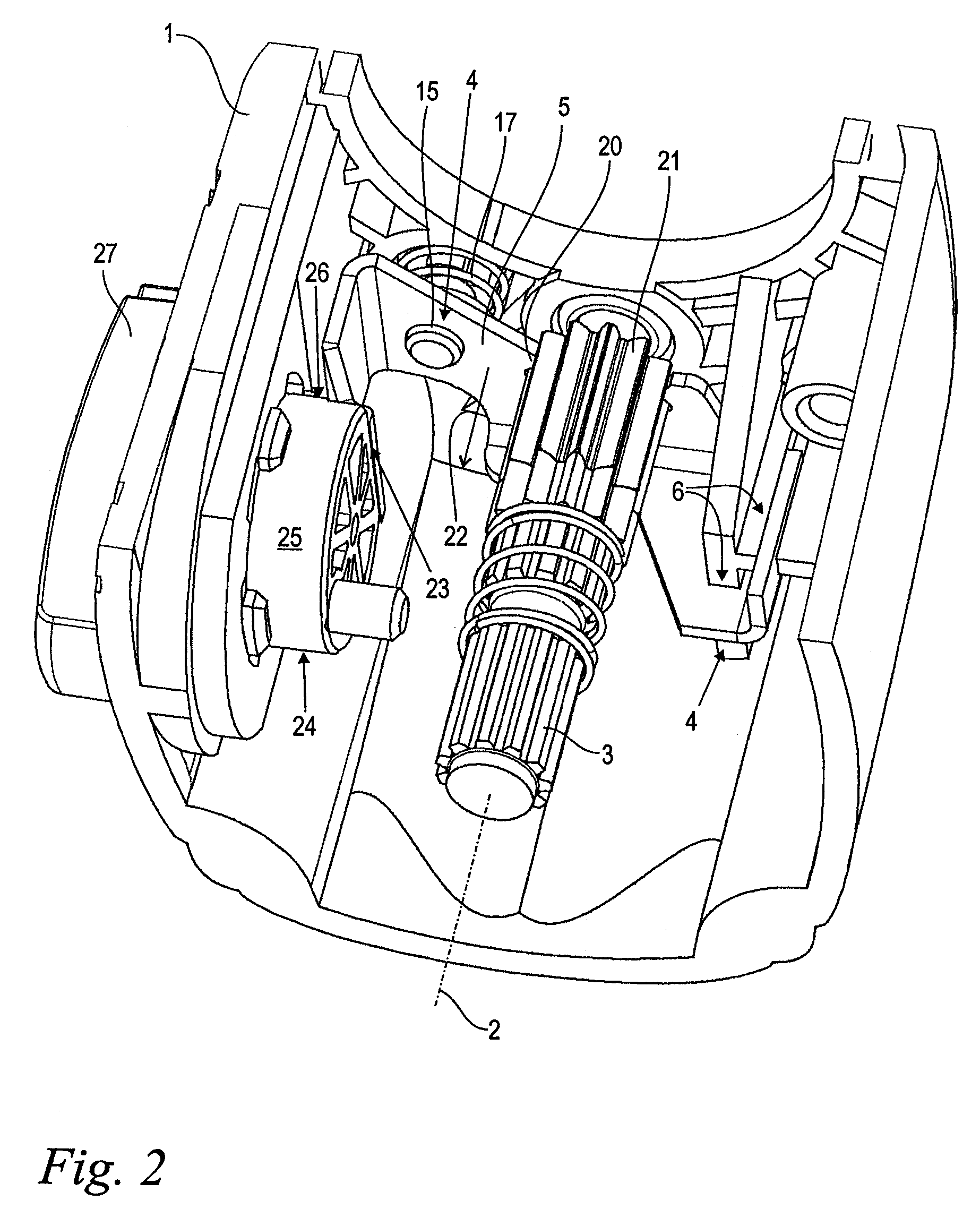
[0019]FIG. 1 shows in a perspective partially sectioned illustration a gearbox housing 1 of a hand-held combination drill and chisel hammer with a spindle lock according to the present invention. The spindle lock comprises the gearbox housing 1, a countershaft 3 that is rotatably supported in the gearbox housing 1 about axis of rotation 2, and a locking plate 5 that is displaceably guided parallel to the axis of rotation 2 in guide means 4 in the gearbox housing 1. On the countershaft 3 a pinion with a circumferential toothing 21 is rotatably supported, wherein the toothing 21 is provided for rotatingly driving the tool spindle (not illustrated) in drill operation as well as combined drill and chisel operation. The locking plate 5 has a cutout with radially inwardly projecting teeth 20; the cutout partially surrounds the countershaft 3 in the illustrated position of the locking plate 5 at the end face of the toothing 21. The teeth 20 are not in engagement with the toothing 21 so tha...


PUM

PropertyMeasurementUnit
degrees of freedomaaaaaaaaaa
rotational movementaaaaaaaaaa
axis of rotationaaaaaaaaaa

Abstract

A spindle lock of a hand-held combination drill and chisel hammer has a gearbox housing and a countershaft rotatably supported in the gearbox housing about an axis of rotation. A locking plate is provided for selectively releasing and locking a rotational movement of the countershaft. Guide elements are disposed in the gearbox housing, wherein the locking plate is displaceably guided on the guide elements in the gearbox housing in a direction parallel to the axis of rotation of the countershaft. The guide elements have a guide rail arrangement wherein a part of the guide rail arrangement is provided on the gearbox housing and is integral with the gearbox housing.

Description

BACKGROUND OF THE INVENTION[0001]The invention relates to a spindle lock of a hand-held combination drill and chisel hammer comprising a gearbox, a countershaft rotatably supported in the gearbox about an axis of rotation, and a locking plate that is guided in guide means within the gearbox parallel to the axis of rotation, wherein the movable locking plate is provided for selectively locking and releasing rotational movement of the countershaft.[0002]A similar spindle lock is disclosed in DE 10 2004 052 329 A1 in which however the tool spindle and not the countershaft can be locked directly by means of a locking plate.[0003]Hand-held combination drill and chisel hammers are operated in different working modes depending on the application. As selected by the operator, the drive motor of the hammer device can either provide purely a rotational movement of the tool spindle for drilling operation, can exclusively drive the hammer action without rotational movement of the tool spindle f...

Claims


Application Information

Patent Timeline
Patent Type & Authority Patents(United States)
IPC IPC(8): E02D7/02
CPCB25D16/006B25F5/001B25D2216/0015Y10T279/20B25D2216/0046B25D2216/0023
Inventor POHL, STEFANHOPP, JURGEN
Owner AEG ELECTRIC TOOLS
Learn More