Bilge pump

a bilge pump and liquid technology, applied in the field of bilge pumps, can solve the problems of difficult installation of bilge pumps, complicated electrical wiring, and difficulty in replacing inoperable bilge pumps, and achieve the effect of convenient connection of bilge pumps and easy installation in boats

Inactive Publication Date: 2010-10-05
SHURFLO
View PDF196 Cites 7 Cited by
  • Summary
  • Abstract
  • Description
  • Claims
  • Application Information

AI Technical Summary

Benefits of technology

[0006]Some embodiments of the present invention alleviate the problems associated with installing new or replacement bilge pumps in confined spaces and with aligning the operative features of the bilge pump (i.e., the electrical leads and the pump outlet nozzle) with the corresponding operative features of the boat (i.e. the electrical supply leads and the drain conduit). The present invention provides a bilge pump that is adaptable to facilitate installation in the boat and to facilitate connection of the bilge pump to the operative features of the boat. The present invention also provides a method for installing and connecting a bilge pump in a boat.
[0008]In another aspect of the invention, a housing is releasably coupled to the base. The housing defines a cavity for receiving a motor. A locking ring is engageable with the motor and the housing to secure the motor in the cavity while allowing the motor to be movable with respect to the housing. In yet another aspect of the invention, the cavity in the housing communicates with an outlet portion that defines a socket. An outlet nozzle having an outlet end is movably received in the socket so that the outlet end can be moved relative to the housing. These aspects, employed individually or in combination, make the bilge pump highly adaptable and facilitate installation.

Problems solved by technology

Installation of bilge pumps is often relatively difficult due to the tight quarters of the engine compartment or bilge area.
Mounting the bilge pump to the hull, connecting the electrical wiring, and connecting the pump outlet to the drain conduit are all complicated by the confined working space.
Replacing an inoperable bilge pump may even be more difficult.
Another problem of existing bilge pumps is related to the manner in which such pumps turn on and off.
Unfortunately, such sensors or switches can react to movement of the boat (and water in the hull) by turning the pump on when the amount of water in the hull is low and / or by turning the pump off when the amount of water in the hull is high.

Method used


Image

  • Bilge pump
  • Bilge pump
  • Bilge pump

Examples


Embodiment Construction

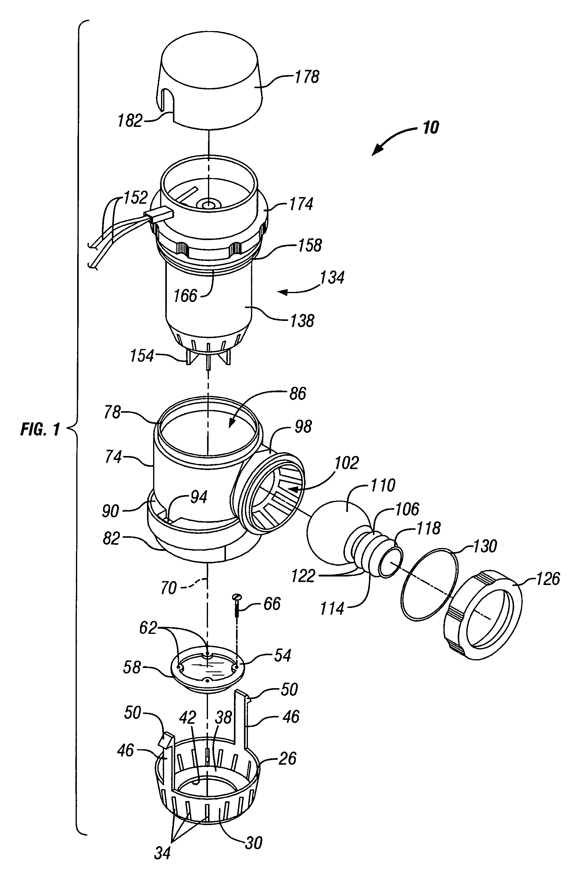
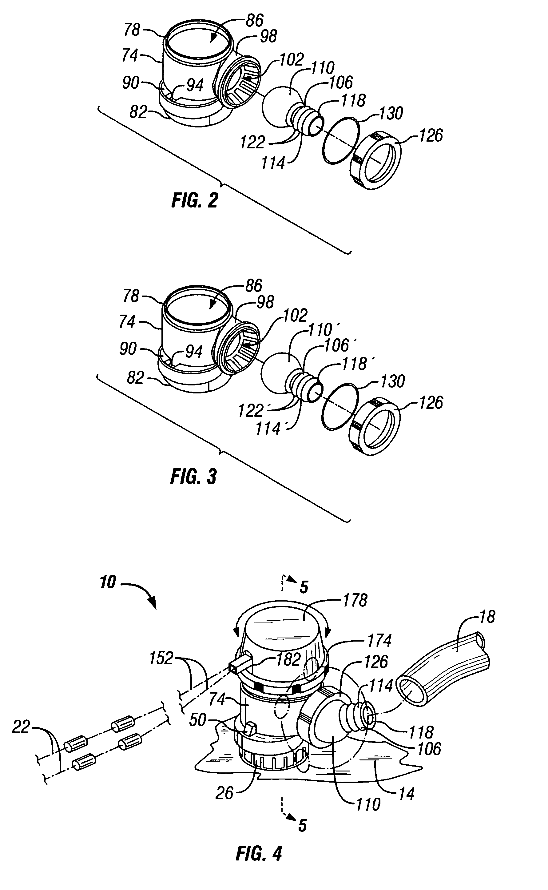
[0025]FIGS. 1-6 illustrate a bilge pump 10 embodying the present invention. The bilge pump 10 is intended for use in a boat or vessel (not shown), however, the bilge pump 10 can also be used with other applications that utilize a pump. As seen in FIG. 4, the vessel includes a mounting surface 14, a drain conduit 18, and at least one electrical power supply lead 22. The mounting surface 14 is typically located in the bilge or engine compartment of the vessel, however the mounting surface 14 can also be found in other locations, such as in a live well. As used herein and in the appended claims, the term “drain conduit” refers to a piece of hose, tubing, piping, or other similar material that defines a pathway for fluid to travel from an interior portion of the vessel to an exterior portion of the vessel, as is well-known to those skilled in the art.

[0026]In the illustrated embodiment, the bilge pump 10 includes a base 26 having a peripheral wall 30. A plurality of apertures 34 are for...


PUM


Abstract

A bilge pump having a mounting member adapted to be mounted to a vessel and a base movably engageable with the mounting member and positionable in at least two positions relative to the mounting member. A housing is releasably coupled to the base and defines a cavity for receiving a motor. A locking ring is engageable with the motor and the housing to secure the motor in the cavity while allowing the motor to be movable with respect to the housing. The cavity in the housing communicates with an outlet portion defining a socket. An outlet nozzle having an outlet end is movably received in the socket so that the outlet end can be moved relative to the housing. These features can be employed individually or in combination to make the bilge pump highly adaptable, thereby facilitating installation.

Description

CROSS REFERENCE TO RELATED APPLICATIONS[0001]This application is a continuation application of U.S. patent application Ser. No. 10 / 013,311, filed Nov. 12, 2001, now U.S. Pat. No. 6,715,994 issued on Apr. 6, 2004.FIELD OF THE INVENTION[0002]The invention relates to pumps, and more particularly to pumps for pumping bilge liquids from a vessel.BACKGROUND OF THE INVENTION[0003]Bilge pumps are employed to remove water and other liquids from boats and are typically mounted in the boat's engine compartment or bilge area. Installation of bilge pumps is often relatively difficult due to the tight quarters of the engine compartment or bilge area. Mounting the bilge pump to the hull, connecting the electrical wiring, and connecting the pump outlet to the drain conduit are all complicated by the confined working space. Replacing an inoperable bilge pump may even be more difficult. Replacement bilge pumps usually have a mounting footprint and overall configuration that is different from the orig...

Claims


Application Information

Patent Timeline
Patent Type & Authority Patents(United States)
IPC IPC(8): F04B49/04F04D29/42
CPCF04B39/121F04B39/14F04D29/4293F04D29/605F04D29/628F04D29/426F04D29/708F05D2250/51F05D2250/52
Inventor PATEL, ANIL B.BABSON, BRIAN A.
Owner SHURFLO
Why Eureka
Try Eureka