
Implant abutment clips

a technology of abutment and abutment, which is applied in the field of dental implants, can solve the problems of limited access in various areas of the mouth, extreme difficulty in handling, and further compounding the difficulty of this process

Active Publication Date: 2010-10-05
IMPLANT INGENUITY
View PDF31 Cites 4 Cited by
  • Summary
  • Abstract
  • Description
  • Claims
  • Application Information

AI Technical Summary

Problems solved by technology

They are therefore extremely difficult to handle as the dental surgeon has to place the screw into a hole on the abutment and then hold both the screw and abutment on the implant post with one finger while trying to line up and begin to engage the threads on the screw with the other hand.
One of the key problems with the above procedure is the extremely limited access in various areas of the mouth, such as the region around the rear molars.
The difficulty of this process is further compounded if the position for the implant is in the upper rear part of the mouth between two teeth.
This position is more difficult because the dental surgeon faces the effects of gravity and, because the position of installation is toward the back of the mouth, there is the further complication of limited vision and access.
The dental surgeon is always concerned that the screw and abutment will fall out of the jawbone before the threads are engaged and that the patient might then accidentally swallow or inhale them.
A second problem experienced by dental surgeons when doing this procedure is the problem of correctly orienting the abutment during installation so as to ensure that the prosthesis will end up in the correct orientation relative to the surrounding teeth.
This does not sound too difficult, but the abutment is so small and the shape and angle so subtle that it is difficult to get the abutment correctly oriented in the mouth.

Method used


Image

  • Implant abutment clips
  • Implant abutment clips
  • Implant abutment clips

Examples


Embodiment Construction

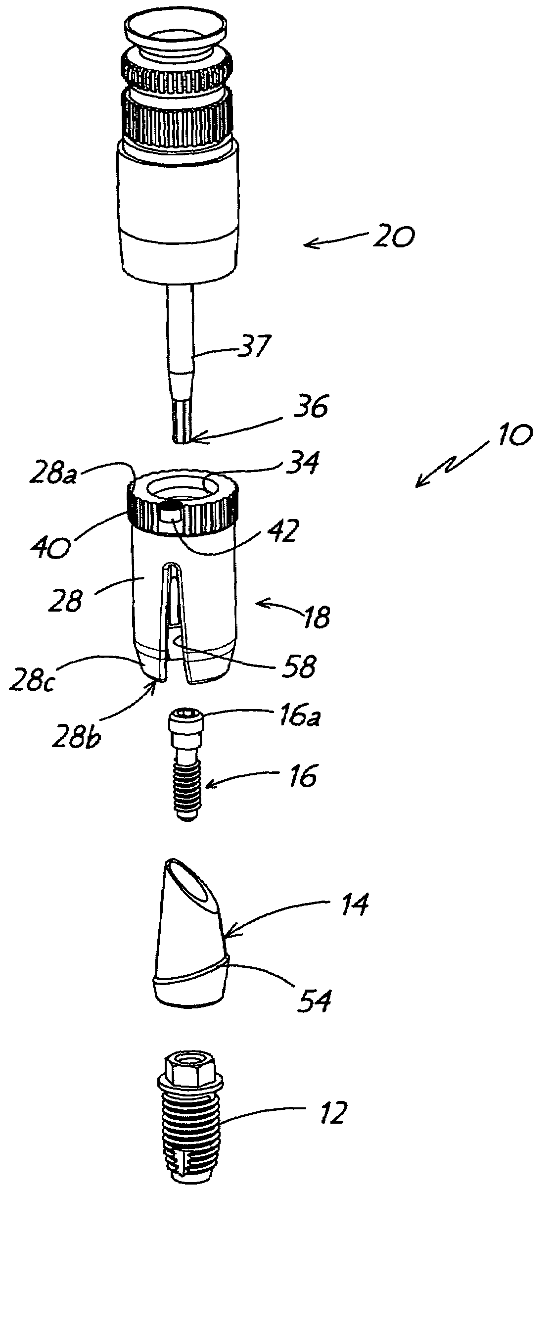
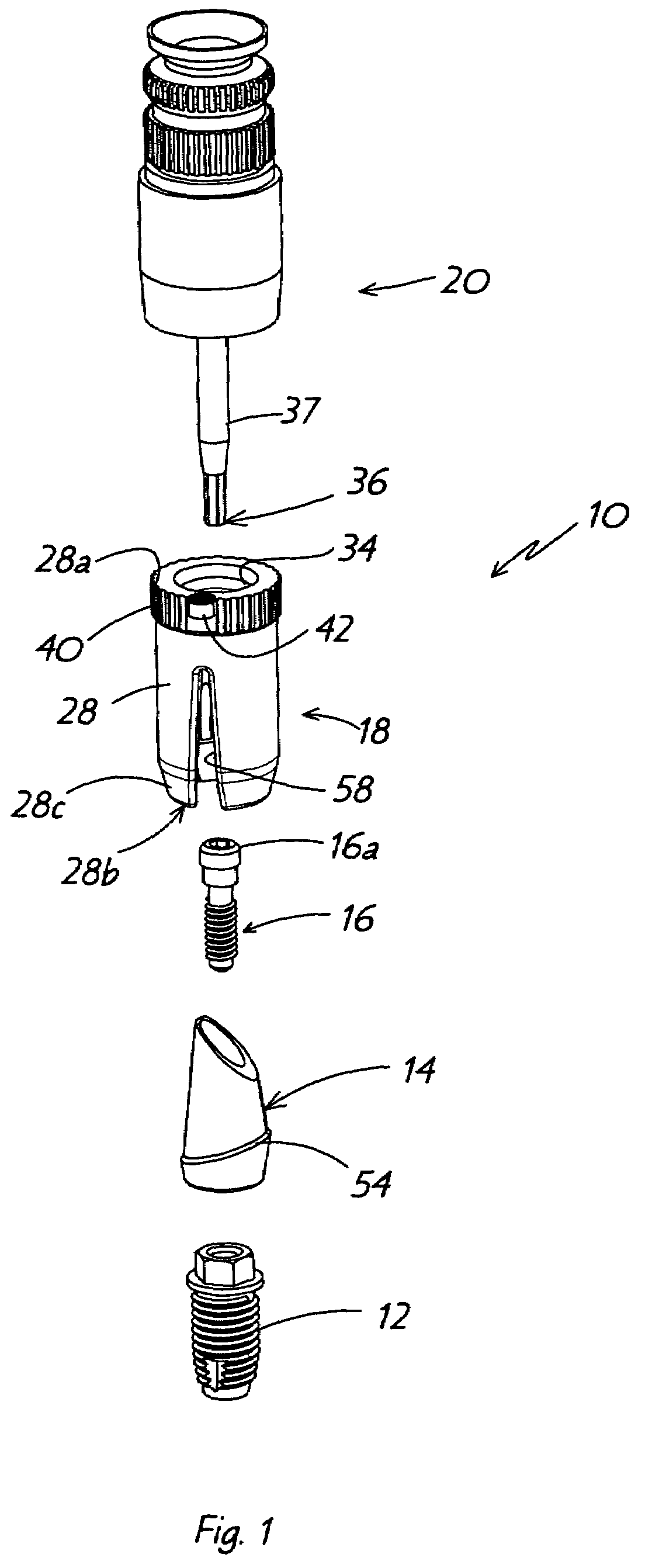
[0027]Referring to FIGS. 1-14, there is shown a dental implant system 10 comprising an implant post 12, an abutment 14, an abutment screw 16, an abutment clip 18 in accordance with the present invention, and a screwdriver 20 for securing the various components together. System 10 is used to install a prosthesis, such as artificial tooth 22 (FIG. 5) into the jaw of a patient. In the attached figures, the jaw illustrated may represent a model 24a (FIG. 2) of a patient's jaw that is used for transporting a manufactured abutment 14 and prosthesis 22 from a laboratory to a dental surgeon, or it may be the actual jaw 24b (FIG. 5) into which the implant and abutment are secured.

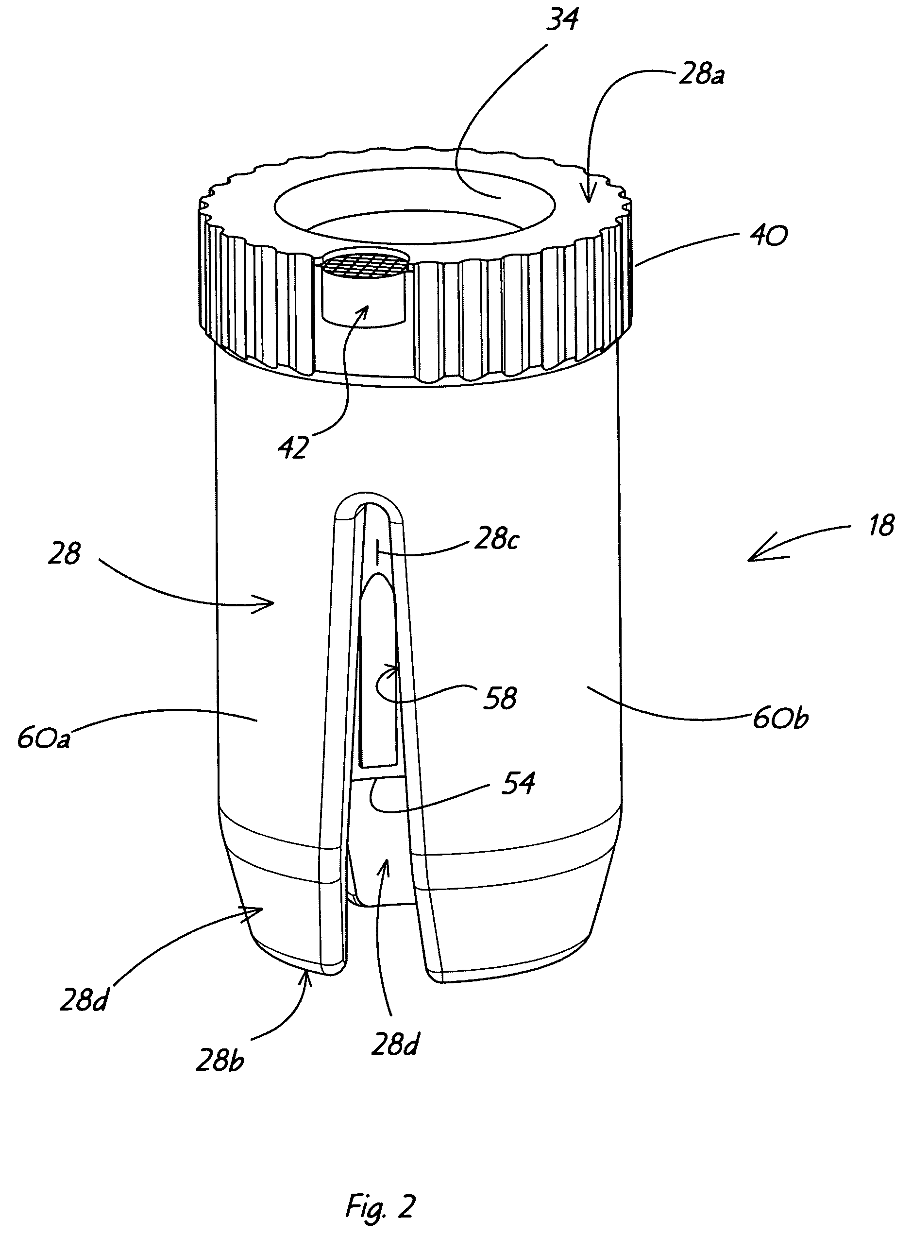
[0028]As shown in FIGS. 2-4, and in accordance with a specific feature of the present invention, an abutment clip 18 is provided to enable a dental surgeon to more accurately identify the orientation that abutment 14 has in jaw 24a and to replicate that orientation when the abutment 14 and prosthesis 22 and position...


PUM


Abstract

An abutment clip for use in a dental implant system for orienting an abutment relative to features on a patient's teeth and jawbone so that a prosthesis, which is attachable to the abutment, will be correctly oriented. The abutment clip comprises a housing that includes a chamber sized to receive the abutment therein. The housing has at least one position indicator provided at one end thereof. The dentist engages the abutment clip over the abutment when it is still attached to a manufacturer's plaster model. He notes the position of the indicator on the housing in reference to features on the model and then detaches the abutment clip, abutment and abutment screw as a unit from the model. The combined abutment clip, abutment and screw are then positioned on an implant post in the patient's jaw bone and the position indicator is used to verify the orientation of the abutment before it is secured to the implant post.

Description

BACKGROUND OF THE INVENTION[0001]1. Technical Field[0002]This invention generally relates to dentistry. More particularly, the invention relates to dental implants. Specifically, the invention relates to an abutment clip that is detachably engageable over an abutment and includes at least one position indicator thereon that aids the dental surgeon in correctly orienting an abutment on an implant post.[0003]2. Background Information[0004]Over the last few decades dental technology has made great strides in providing improved ways to give people more natural-appearing and better secured artificial teeth or bridgework. (For the sake of clarity, both single artificial teeth and bridgework will be referred to hereinafter as “a prosthesis”). One of those improved technologies utilizes dental implants. A dental implant is a small titanium screw or bolt that is secured into the jaw bone to act as an anchor for a prosthesis. The implants are installed by drilling a small hole in the patient'...

Claims


Application Information

Patent Timeline
Patent Type & Authority Patents(United States)
IPC IPC(8): A61C8/00
CPCA61C8/0089
Inventor SCHAFFRAN, ALLANWONG, ANDY DOUG-LUNDICKIE, ROBERT G.
Owner IMPLANT INGENUITY
Learn More