Continuously variable transmission and control method thereof

a transmission and continuously variable technology, applied in the direction of gearing control, gearing elements, gearing, etc., can solve the problems of excessive line pressure and fuel economy degradation, and achieve the effects of preventing excessive line pressure, reducing oil temperature and reducing fuel consumption

Active Publication Date: 2010-10-05
JATCO LTD +1
View PDF7 Cites 12 Cited by
  • Summary
  • Abstract
  • Description
  • Claims
  • Application Information

AI Technical Summary

Benefits of technology

[0007]This invention has been designed to solve this problem, and it is an object thereof to prevent excessive line pressure in a high load state, thereby improving the fuel economy and suppressing oil temperature increases.
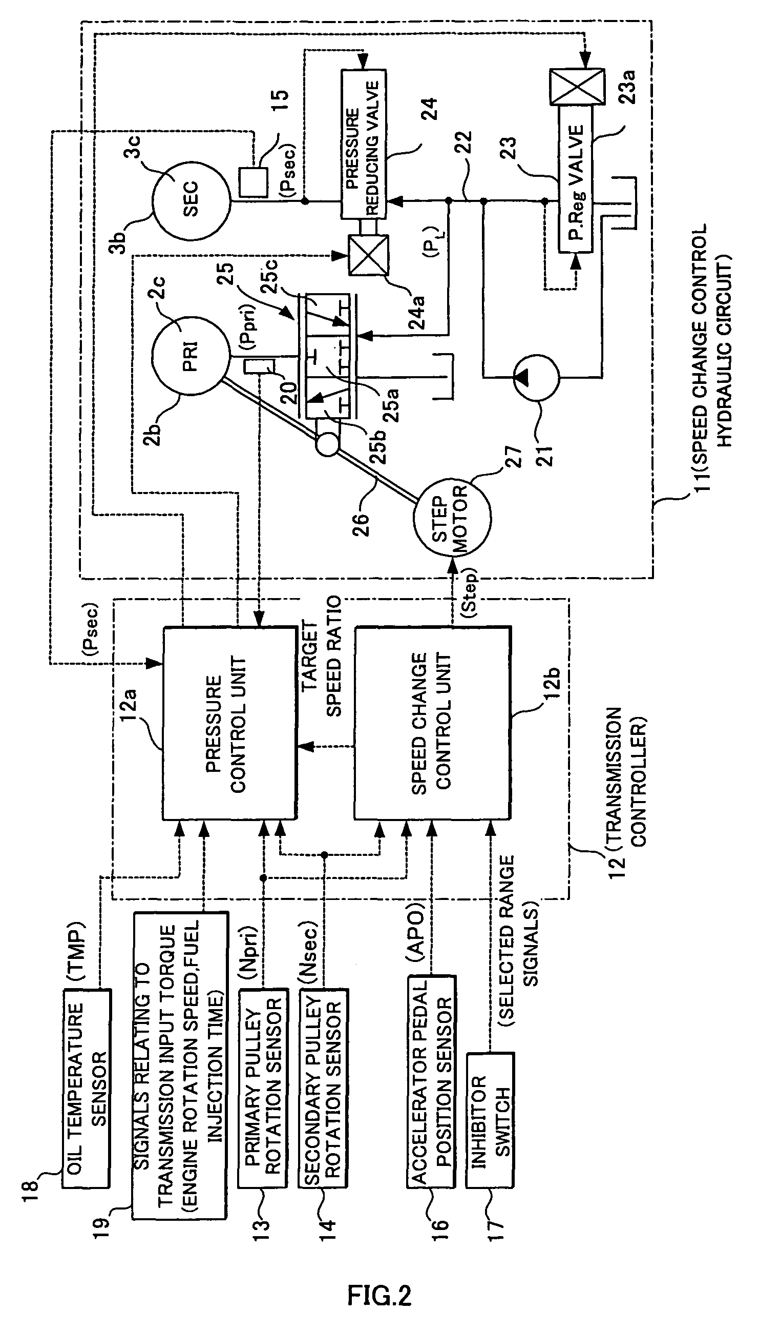
[0010]According to this invention, when the primary pulley input torque increases, the actuator operating position deviation correction amount is calculated to be large, and the line pressure is controlled on the basis of the reference model operating position of the actuator, which corresponds to the target speed ratio, the actual operating position of the actuator, which is determined from the actual speed ratio, and the actuator operating position deviation correction amount. As a result, excessive line pressure can be prevented from occurring on the high torque side, the fuel economy can be improved, and oil temperature increases can be suppressed.

Problems solved by technology

However, when the engine torque increases in the prior art described above, i.e. in a high load state, the line pressure is raised even when the line pressure is sufficient in reality, leading to an excessive line pressure and deterioration of the fuel economy.

Method used


Image

  • Continuously variable transmission and control method thereof
  • Continuously variable transmission and control method thereof
  • Continuously variable transmission and control method thereof

Examples


Embodiment Construction

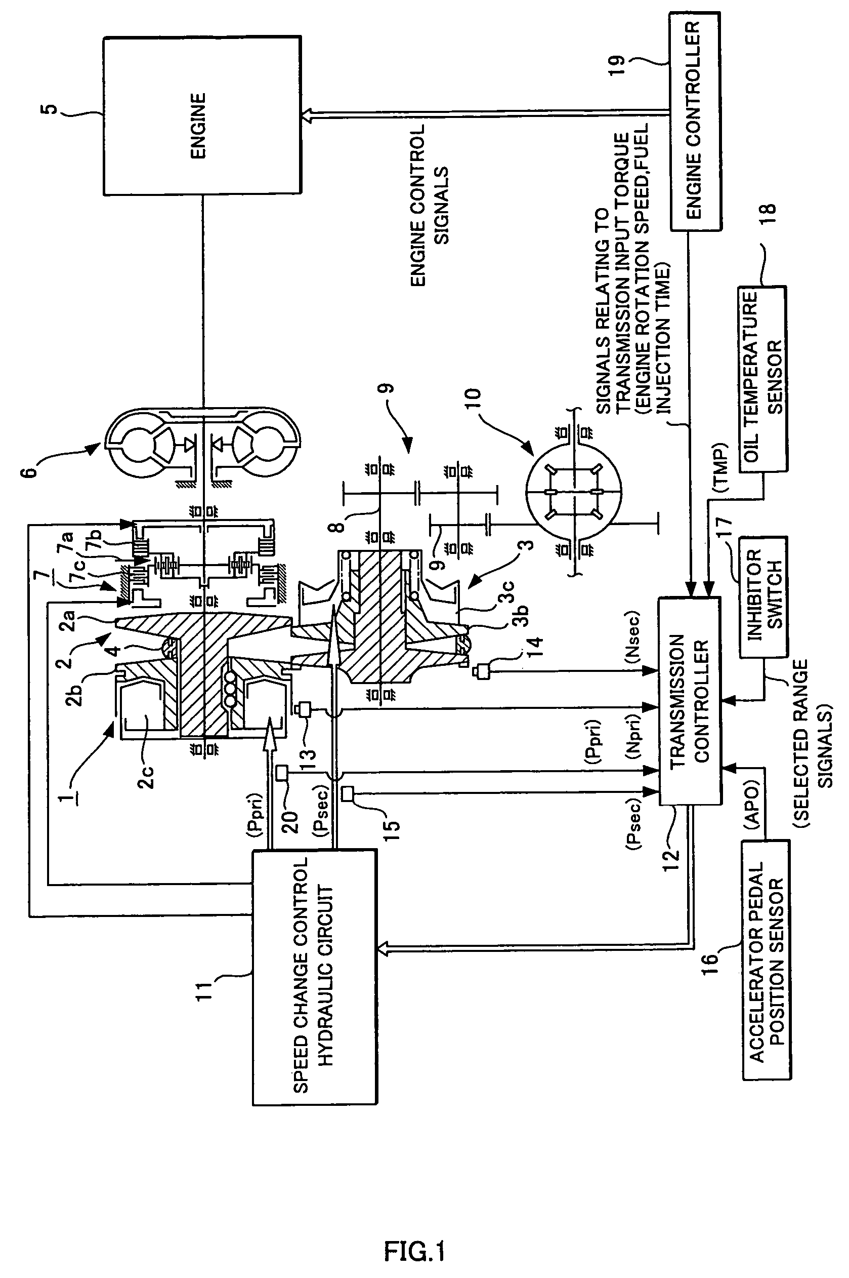
[0020]An embodiment of this invention will be described in detail below on the basis of the drawings. FIG. 1 shows an outline of a V belt continuously variable transmission 1. The V belt continuously variable transmission comprises a primary pulley 2 and a secondary pulley 3 arranged such that the V grooves of the two are aligned, and a V belt (belt) 4 which is wrapped around the V grooves of the pulleys 2, 3. An engine 5 is disposed coaxial with the primary pulley 2, and a torque converter 6 comprising a lockup clutch and a forward-reverse switching mechanism 7 are provided between the engine 5 and primary pulley 2 in succession from the engine 5 side.

[0021]The forward-reverse switching mechanism 7 comprises a double pinion planetary gear set 7a as a principal constitutional element, the sun gear thereof being joined to the engine 5 via the torque converter 6 and the carrier thereof being joined to the primary pulley 2. The forward-reverse switching mechanism 7 further comprises a ...


PUM


Abstract

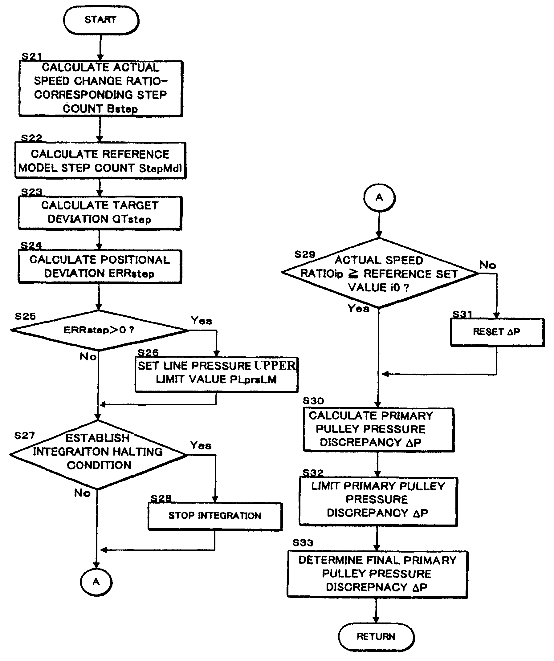
A positional deviation ERRstep of a step motor 27 is calculated on the basis of a reference model step StepMdl, an actual speed ratio-corresponding step Bstep, and an added value obtained by adding together a target deviation GTstep, calculated in accordance with a transmission input torque Ti, and a starting learned value Gstep. When the transmission input torque Ti is large, the target deviation GTstep is increased in accordance with the transmission input torque Ti. A line pressure PL is then controlled on the basis of the positional deviation ERRstep obtained as a result.

Description

FIELD OF THE INVENTION[0001]This invention relates to a line pressure control for a continuously variable transmission.BACKGROUND OF THE INVENTION[0002]A continuously variable transmission performs power transmission by means of a V belt, for example, which is wrapped around a primary pulley into which an engine rotation is input and a secondary pulley on an output side which is joined to a vehicle wheel.[0003]In a continuously variable transmission, the step count of a step motor is controlled to realize a target speed ratio, and as a result, the pressure of the primary pulley is controlled.[0004]JP2004-100736A discloses a conventional device which, when controlling a line pressure serving as the source pressure of a primary pulley pressure and a secondary pulley pressure of a continuously variable transmission, takes a line pressure discrepancy caused by an error in the attachment of the step motor into account.SUMMARY OF THE INVENTION[0005]However, when the engine torque increase...

Claims


Application Information

Patent Timeline
Patent Type & Authority Patents(United States)
IPC IPC(8): F16H61/02
CPCF16H61/66272Y10T477/624F16H2342/044F16H61/02F16H9/00F16H61/00F16H59/00
Inventor IZUMI, TETSUYANIHEI, HIRONORIKIM, SEONJAEHOSHI, NAOHIROLEE, KWANG-HO
Owner JATCO LTD
Why Eureka
Try Eureka