Low power, self-gated, pulse triggered clock gating cell

a clock gating cell, low power technology, applied in the direction of pulse technique, pulse characteristics measurement, generating/distributing signals, etc., can solve the problems of power loss, power loss in the conventional clock gating cell, and power loss caused by power loss

Active Publication Date: 2010-10-05
NXP USA INC
View PDF5 Cites 8 Cited by
  • Summary
  • Abstract
  • Description
  • Claims
  • Application Information

AI Technical Summary

Problems solved by technology

Therefore, providing a continuous clock signal to the clock input of such storage elements results in power loss.
The power loss is caused by the repetitive charging and discharging of the capacitive load associated with the clock input of the storage elements.
The continuous switching of CLK_IN causes continuous charging and discharging of the capacitive load associated with the clock input stage 106, thereby causing power loss in the conventional clock gating cell 100.

Method used


Image

  • Low power, self-gated, pulse triggered clock gating cell
  • Low power, self-gated, pulse triggered clock gating cell
  • Low power, self-gated, pulse triggered clock gating cell

Examples


Embodiment Construction

[0016]The detailed description of the appended drawings is intended as a description of the currently preferred embodiments of the present invention, and is not intended to represent the only form in which the present invention may be practiced. It is to be understood that the same or equivalent functions may be accomplished by different embodiments that are intended to be encompassed within the spirit and scope of the present invention.

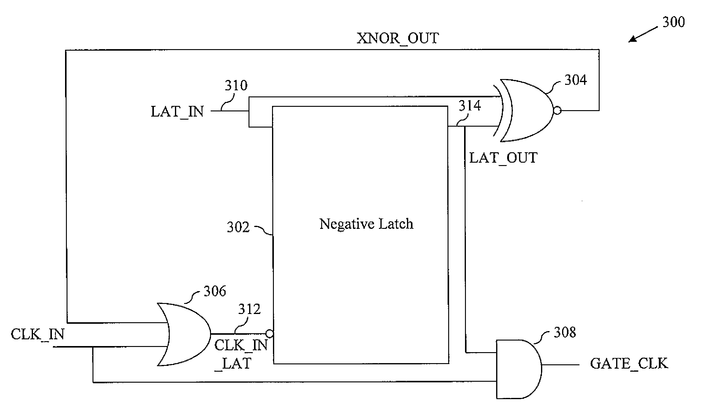
[0017]In an embodiment of the present invention, a clock gating cell for generating a gated clock signal is provided. The clock gating cell includes a latch circuit having at least one input stage that receives an input signal, a clock input stage that receives a latch clock signal, and at least one output stage that provides an output signal. The output signal changes based on the input signal and the latch clock signal. Further, the clock gating cell includes a comparison logic circuit, a first logic circuit, and a second logic circuit. The compari...


PUM


Abstract

A clock gating cell for gating clock signals includes a latch circuit, a comparison logic circuit, a first logic circuit, and a second logic circuit. An input signal is provided to the latch circuit. An input clock signal is provided to the first logic circuit. The first logic circuit switches the input clock signal based on a comparison signal generated by the comparison logic circuit, thereby generating a latch clock signal. The latch clock signal switches between a first state and a second state only when the input signal switches between the first state and the second state, thereby preventing power loss of the clock gating cell.

Description

BACKGROUND OF THE INVENTION[0001]The present invention relates generally to digital circuits, and more specifically, to clock gating cells used in digital circuits.[0002]A clock signal is used in a digital circuit to synchronize the operation of various functional blocks of the digital circuit. A functional block may include a plurality of storage elements such as flip-flops or latches. A storage element changes its output based on a change in the levels of the clock signal that is received at a clock input of the storage element. However, during certain stages of the operation, storage elements in the functional blocks are not required to change their states based on the switching of the clock signal. Therefore, providing a continuous clock signal to the clock input of such storage elements results in power loss. The power loss is caused by the repetitive charging and discharging of the capacitive load associated with the clock input of the storage elements.[0003]Therefore, in orde...

Claims


Application Information

Patent Timeline
Patent Type & Authority Patents(United States)
IPC IPC(8): H03K19/00H03K5/05
CPCG06F1/04H03K5/1252H03K19/0016
Inventor SRIVASTAVA, ANUBHAVMAHAJAN, ABHISHEKSRIVASTAVA, NEHA
Owner NXP USA INC
Why Eureka
Try Eureka