
System memory map decoder logic

a decoder logic and memory map technology, applied in the field of system memory map decoder logic, can solve the problems of inefficiency of conventional mechanisms for performing decoder operations, and achieve the effect of reducing system resource usage and critical path delay

Inactive Publication Date: 2010-10-05
ALTERA CORP
View PDF6 Cites 5 Cited by
  • Summary
  • Abstract
  • Description
  • Claims
  • Application Information

AI Technical Summary

Benefits of technology

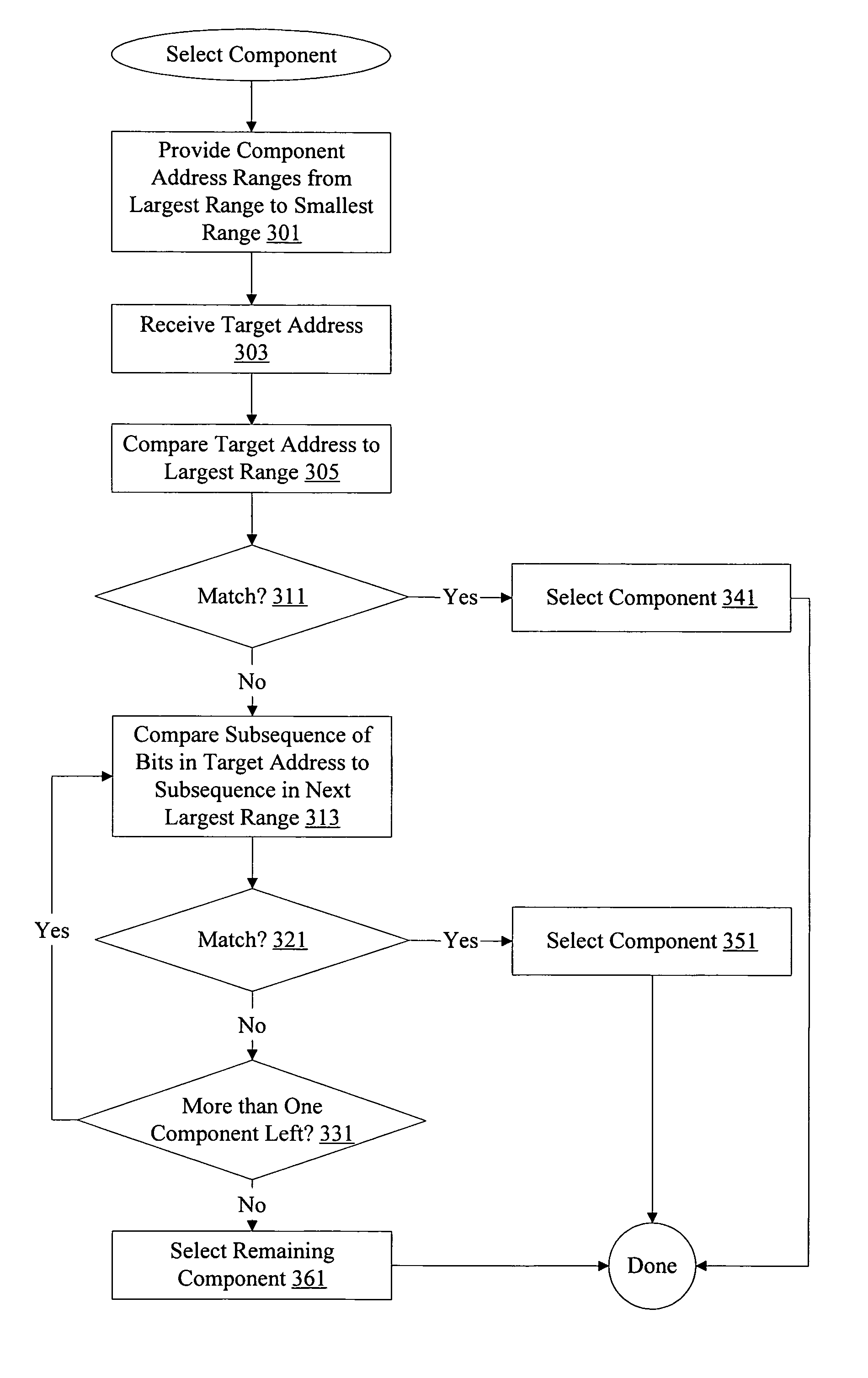
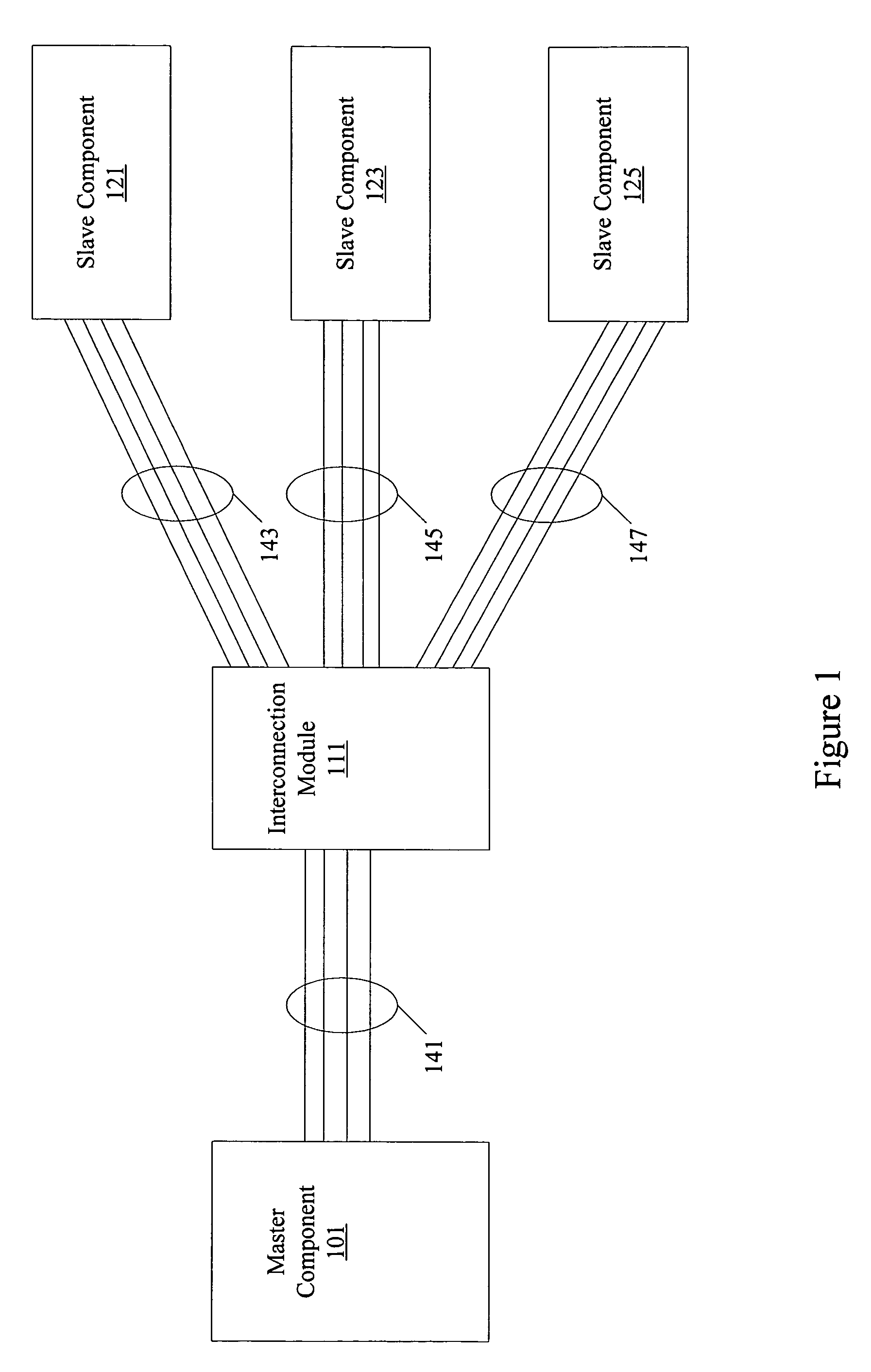
[0007]Methods and apparatus are provided optimizing system memory map decoder logic. A system is configured with multiple master and slave components. Using information known about the system configuration, optimized decoder logic can be configured. Critical path delay and system resource usage are reduced by optimizing decoder logic.

Problems solved by technology

However, conventional mechanisms for performing decoder operations are inefficient.

Method used


Image

  • System memory map decoder logic
  • System memory map decoder logic
  • System memory map decoder logic

Examples


Embodiment Construction

[0019]Reference will now be made in detail to some specific embodiments of the invention including the best modes contemplated by the inventors for carrying out the invention. Examples of these specific embodiments are illustrated in the accompanying drawings. While the invention is described in conjunction with these specific embodiments, it will be understood that it is not intended to limit the invention to the described embodiments. On the contrary, it is intended to cover alternatives, modifications, and equivalents as may be included within the spirit and scope of the invention as defined by the appended claims. For example, the techniques of the present invention will be described in the context of particular processors and memory.

[0020]However, it should be noted that the techniques of the present invention can be applied to a variety of types of devices. In the following description, numerous specific details are set forth in order to provide a thorough understanding of the...


PUM


Abstract

Methods and apparatus are provided optimizing system memory map decoder logic. A system is configured with multiple master and slave components. Using information known about the system configuration, optimized decoder logic can be configured. Critical path delay and system resource usage are reduced by optimizing decoder logic.

Description

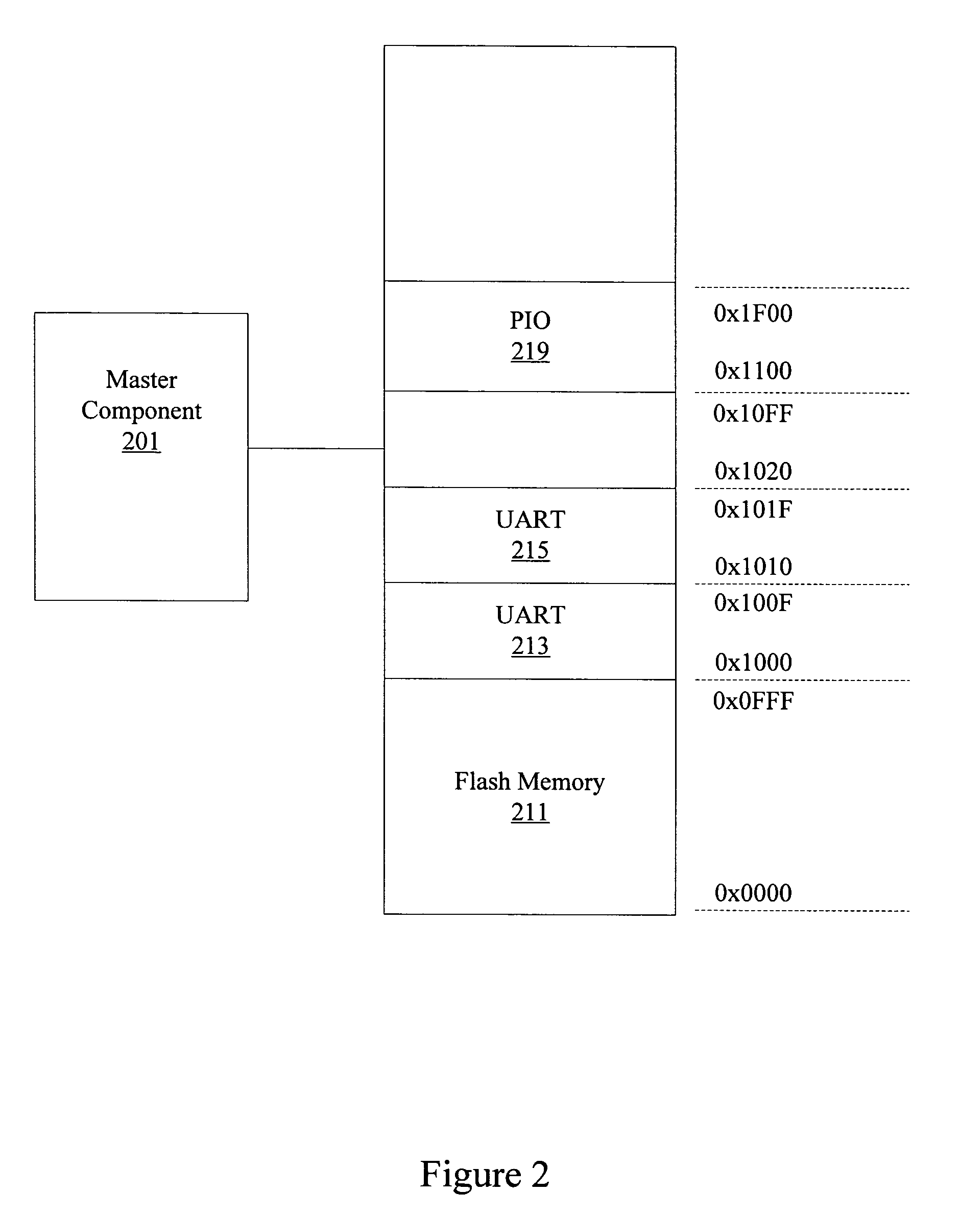
BACKGROUND OF THE INVENTION[0001]1. Field of the Invention[0002]The present invention relates to system memory maps. In one example, the present invention relates to methods and apparatus for optimizing decoder logic associated with a system memory map.[0003]2. Description of Related Art[0004]Conventional processing systems include a variety of components. Master components such as processors and Ethernet components are configured to access a variety of slave components such as memory, timers, interface ports, etc. Master components are typically operable to access slave components by using a system memory map.[0005]A system memory map shows a variety of components assigned to various address ranges within system memory. To access a particular slave component, a processor can perform read and write accesses to a particular range of addresses in memory. In conventional systems, decoder logic performs address comparisons to determine what component is being accessed.[0006]However, con...

Claims


Application Information

Patent Timeline
Patent Type & Authority Patents(United States)
IPC IPC(8): G06F13/14
CPCG06F13/368G06F13/4265
Inventor PRITCHARD, JEFFREY ORIONHUTKINS, PETER
Owner ALTERA CORP
Learn More