Portable rock crusher and scarifier

a rock crusher and portable technology, applied in the field of hard material disintegration machines, can solve the problems of limited mounting patterns of tooling implements, wear and tear of arbors and tooling implements, and inability to mill surfaces, so as to increase operator visibility

Active Publication Date: 2010-10-12
LCIP LLC
View PDF18 Cites 10 Cited by
  • Summary
  • Abstract
  • Description
  • Claims
  • Application Information

AI Technical Summary

Benefits of technology

[0019]a further object to provide such a portable rock crusher and scarifier having a power pack carried rearward of the crusher frame to increase operator visibility, to move the center of gravity rearward and to allow carriage by a variety of road maintenance vehicles.
[0028]a still further object to provide such a portable rock crusher and scarifier that is of new and novel design, of rugged and durable nature, of simple and economic manufacture and one that is otherwise well suited to the uses and purposes for which it is intended.

Problems solved by technology

Rock crushers and scarifiers are essential for building, maintaining and reconditioning roads but have various inherent drawbacks including rapid arbor and tooling implement wear, they are either mobile or stationary but are generally not operable in both configurations, they have limited tooling implement mounting patterns and they typically cannot mill surfaces to depths below the surrounding frame structure.
Two way transport of the raw and finished material increases costs, decreases efficiency and requires additional road maintenance equipment.
Smaller vehicle supported rock crushers are known to have an integral power source forward of a rotating arbor which places the machine's center of gravity forwardly necessitating large support vehicles to counteract the weight and leading to limited operator visibility which increases risk of accidents and injury.
Known stationary rock crushers and known mobile rock crushers are designed for crushing fractureable material such as rock and gravel and the like but are not well suited for the milling operations without undergoing significant customization.
Further, known stationary and mobile rock crushers typically have a fixed geometry that limits how the machine is used, what type of raw material may be crushed and the characteristics of the finished product, such as size.

Method used


Image

  • Portable rock crusher and scarifier
  • Portable rock crusher and scarifier
  • Portable rock crusher and scarifier

Examples


Embodiment Construction

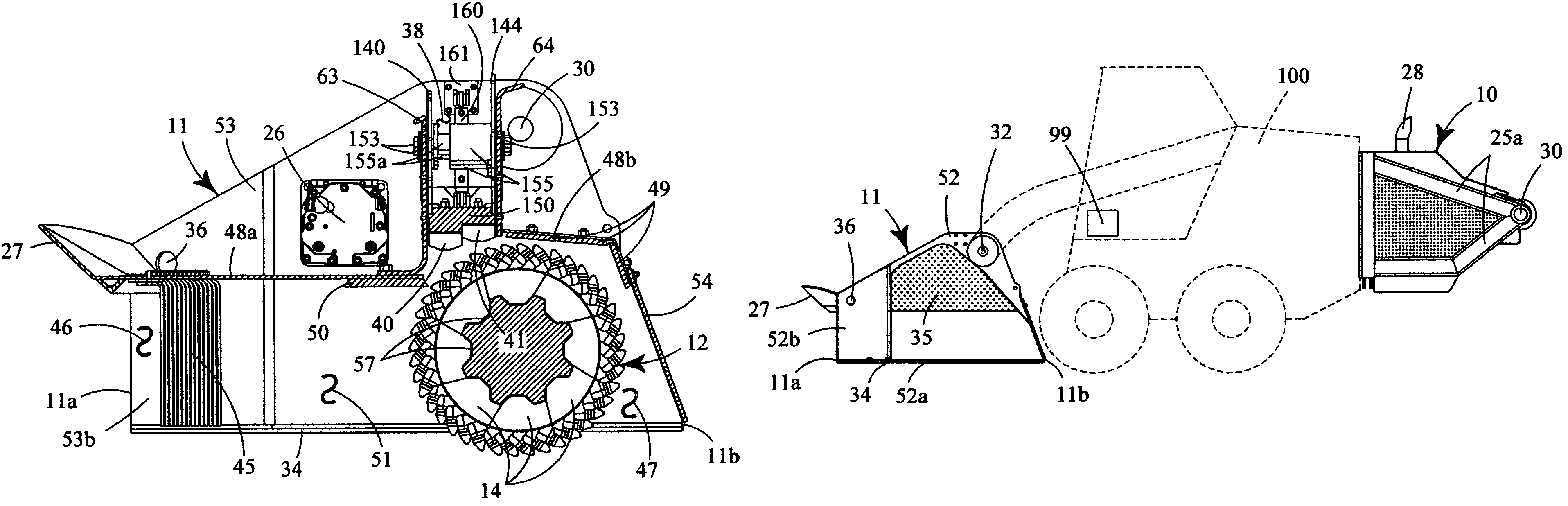
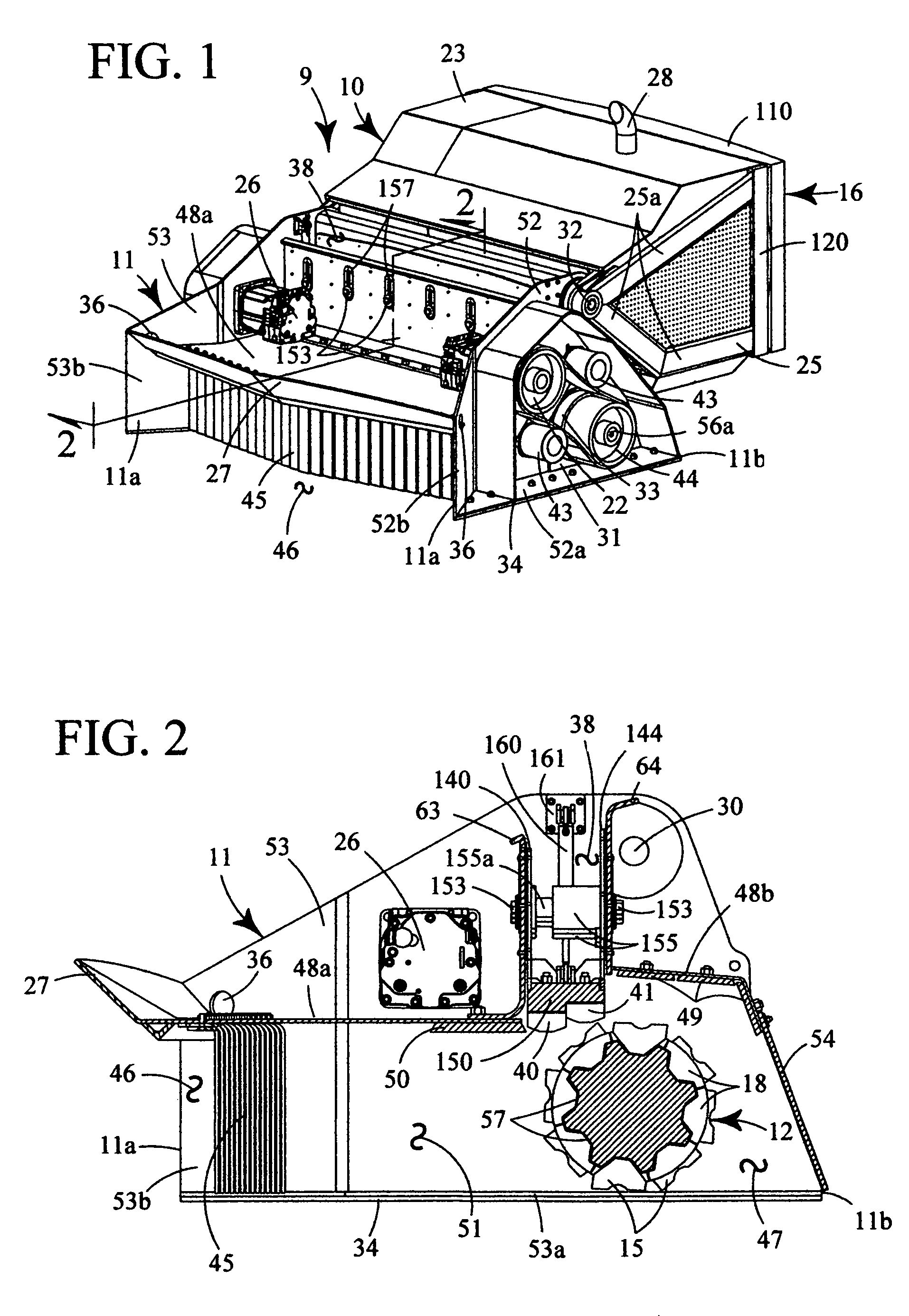
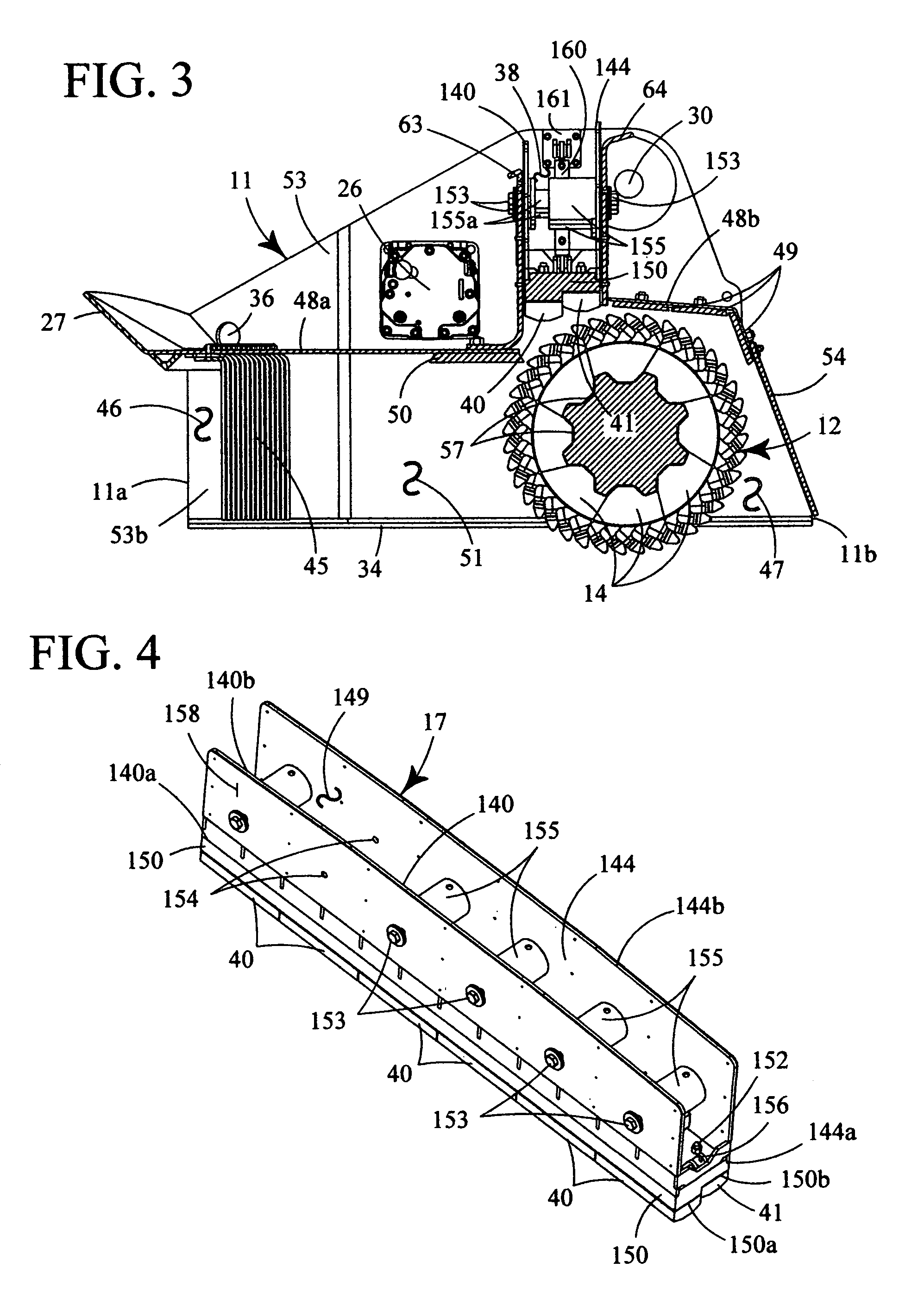
[0052]As used herein, the term “bottom”, its derivatives, and grammatical equivalents refers to the portion of our portable rock crusher and scarifier that is closest to a supporting surface, such as a road bed. The term “top”, its derivatives, and grammatical equivalents refers to the portion of our portable rock crusher and scarifier that is most distant from the supporting surface. The term “rearward”, its derivatives, and grammatical equivalents refers to the portion of our portable rock crusher and scarifier that is closest to a carrying vehicle. The term “forward”, its derivatives, and grammatical equivalents refers to the portion of our portable rock crusher and scarifier that is most distant from the carrying vehicle. The term “outer”, its derivatives, and grammatical equivalents refers to a side portion of our portable rock crusher and scarifier as opposed to a laterally medial portion.

[0053]Our portable rock crusher and scarifier 9 generally provides canting mounting struc...


PUM

PropertyMeasurementUnit
shearing forcesaaaaaaaaaa
force of gravityaaaaaaaaaa
depthsaaaaaaaaaa

Abstract

A portable rock crusher and scarifier for in-situ and on-site crushing, milling, grinding and preparation of road beds having a crusher frame defining a crusher channel journaling a reversibly rotatable arbor carrying plural automatically centering tooling implements in symmetrically spaced V-shaped axial keyways and a power pack releasably attachable to a road maintenance vehicle. An anvil weldment channel defined by spaced apart strongbacks communicates with the crusher channel and carries an adjustably positionable anvil weldment carrying two vertically spaced adjacent anvils proximate the arbor. A canting mounting structure provides attachment to a variety of road maintenance vehicles to provide carriage, support and movement. Milling implements may be installed on the arbor for grinding surfaces at depths below the crusher frame, and the crusher frame and power pack may be attached to a base for stationary operation.

Description

RELATED APPLICATIONS[0001]This application claims the benefit of earlier filed U.S. Provisional Application No. 60 / 903,512 filed on Feb. 27, 2007.BACKGROUND OF INVENTION[0002]1. Field of Invention[0003]This invention relates to hard material disintegration machines, and more particularly to a portable rock crusher and scarifier having a rotating arbor adaptable to crush, grind, scarify and mill material in-situ and on-site for building, maintaining, and reconditioning roadways and for road site development.[0004]2. Background and Description of Prior Art[0005]Rock crushers and scarifiers are essential for building, maintaining and reconditioning roads but have various inherent drawbacks including rapid arbor and tooling implement wear, they are either mobile or stationary but are generally not operable in both configurations, they have limited tooling implement mounting patterns and they typically cannot mill surfaces to depths below the surrounding frame structure.[0006]Stationary ...

Claims


Application Information

Patent Timeline
Patent Type & Authority Patents(United States)
IPC IPC(8): E01C19/05
CPCB02C13/09B02C13/2804B02C21/026B28D1/188E01C19/05E01C19/466E01C23/088E02F3/407E02F7/06E01C2301/06
Inventor CLARK, CEDRIC J.CLARK, CRISTAN J.
Owner LCIP LLC
Why Eureka
Try Eureka