Rolling bearing device for supporting pinion shaft

a bearing device and pinion shaft technology, applied in mechanical equipment, gearing details, gearing, etc., can solve the problems of large rotational torque and torque loss, and achieve the effect of reducing torque loss, reducing torque loss, and reducing oil agitation loss

Inactive Publication Date: 2010-10-12
JTEKT CORP
View PDF28 Cites 3 Cited by
  • Summary
  • Abstract
  • Description
  • Claims
  • Application Information

AI Technical Summary

Benefits of technology

[0026]It is therefore an object of this invention to provide a bearing device in which passing oil in the interior of a bearing is eliminated, thereby reducing a torque loss due to the agitating of such passing oil, and besides in order that insufficient lubrication will not occur in the interior of the bearing as a result of eliminating the passing oil in the interior of the bearing, the bearing is suitably lubricated so as to enhance the rotating performance of the bearing.
[0031]In the first aspect of the invention, the second bearing internal space is sealed, and therefore even when the pinion shaft rotates about its axis, a pumping action will not be produced by the relative rotation of the inner and outer rings, the rolling motion of the ball row, etc., and oil will not flow into the first and second bearing internal spaces, and an oil agitation loss imposed on the first and second ball rows is reduced to a minimum, so that a torque loss can be positively reduced.
[0035]In this case, preferably, an almost half area or more on the outer ring side hemisphere surface of each ball in the first ball row is exposed on the side of the pinion gear. Namely, each ball of the first ball row is preferably exposed such that a median plane of the ball perpendicular to the axis of the bearing (that is, perpendicular to the axis of the pinion shaft) is located at the end surface of the outer ring on the side of the pinion gear or near to the pinion gear in the axial direction. With this exposure arrangement, oil spattered by the rotating pinion gear can effectively deposit on the first row of balls.
[0042]In the second aspect of the invention, apart of the double row rolling bearing (i.e. pinion gear-side portion) is formed into the single angular contact ball bearing construction, and with this construction the single angular contact ball bearing can bear a radial load and an axial load acting in one direction. Also, the cylindrical roller bearing can bear a radial load, and also can provide radial rigidity. And besides, the cylindrical roller bearing does not produce an oil pumping action, and therefore the flowing of the oil into and out of a bearing internal space is eliminated, thus eliminating an oil agitation loss as encountered in the conventional construction, so that a torque loss can be positively reduced.
[0043]In the bearing devices of the present invention, the oil pumping action in the interior of the bearing is eliminated, and therefore even when the pinion shaft rotates about its axis, oil will not flow into the interior of the bearing, and the oil agitation loss in the interior of the bearing can be reduced to a minimum, thereby positively and sufficiently reducing a torque loss.
[0044]In the invention, a torque loss can be positively and sufficiently reduced by eliminating the introduction of passing oil into the interior of the bearing, and besides in order that lubrication in the interior of the bearing will not become insufficient because of this construction, the interior of the bearing can be lubricated so as to enhance the rotating performance of the bearing device.

Problems solved by technology

Therefore, a large frictional resistance acts on this tapered roller bearing, so that a rotational torque is large.
By this pumping action, an excessive amount of oil larger than the required amount for lubrication purposes passes through the bearing in the directions of the arrows, and because of this excess passing oil, an oil agitation loss in the interior of the double row rolling bearing 10 increases, and this causes a torque loss.

Method used


Image

  • Rolling bearing device for supporting pinion shaft
  • Rolling bearing device for supporting pinion shaft
  • Rolling bearing device for supporting pinion shaft

Examples


first embodiment

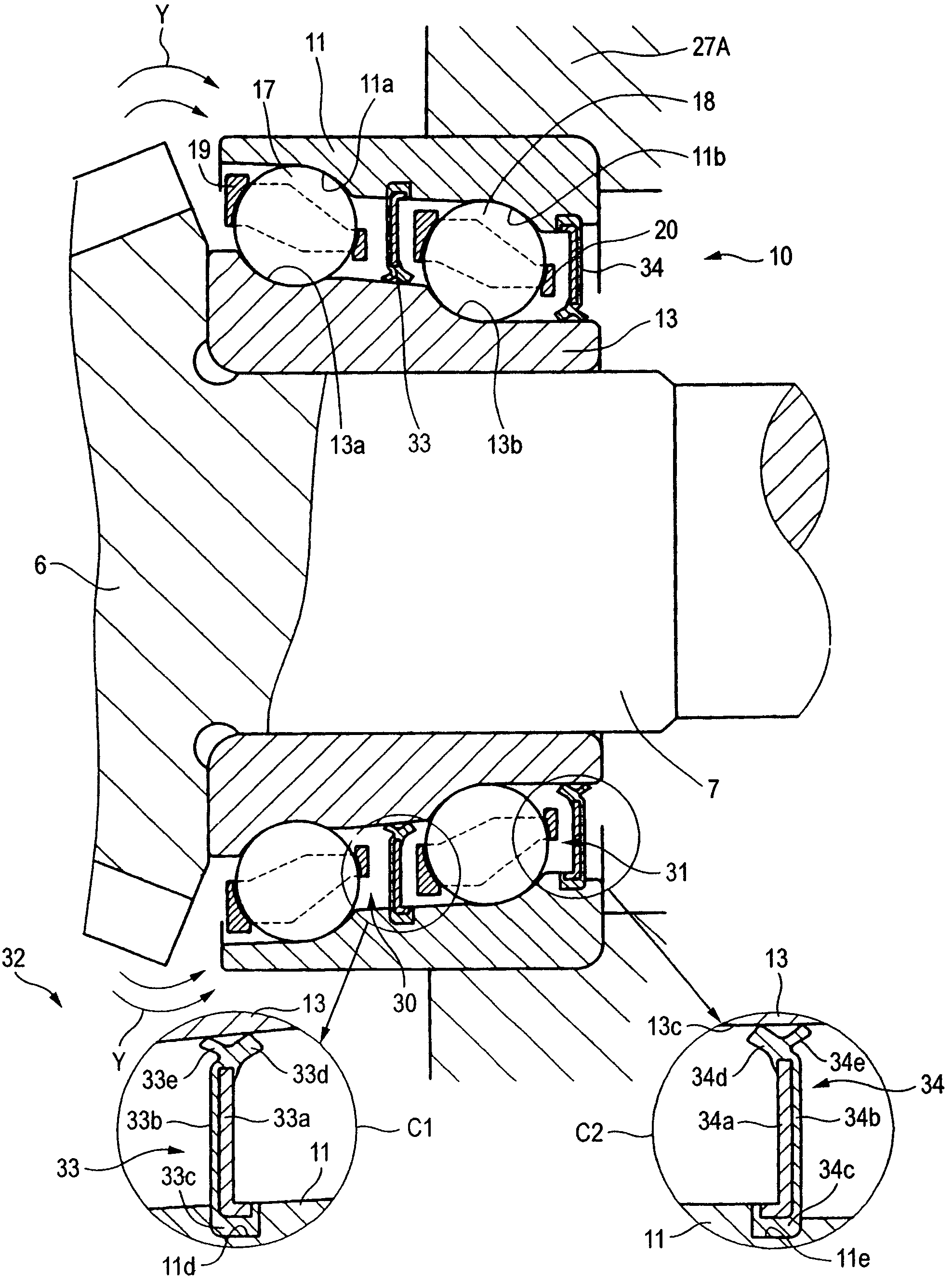
[0054]A first embodiment of a bearing device of the invention will now be described with reference to FIG. 1. FIG. 1 shows only an important portion of this bearing device, and those portions thereof similar to corresponding portions of the conventional example will be designated by identical reference numerals, respectively.

[0055]In the first embodiment, a pinion gear-side double row rolling bearing 10 is in the form of a double row angular contact ball bearing.

[0056]Referring again to this construction, an outer ring 11 has two axially-arranged raceways, that is, a larger-diameter raceway 11a and a smaller-diameter raceway 11b. An inner ring 13 has two axially-arranged raceways, that is, a larger-diameter raceway 13a and a smaller-diameter raceway 13b. A first row 17 of balls are disposed between the raceways 11a and 13a, and a second row 18 of balls are disposed between the raceways 11b and 13b. The ball rows 17 and 18 are held by cages 19 and 20, respectively.

[0057]In the double...

second embodiment

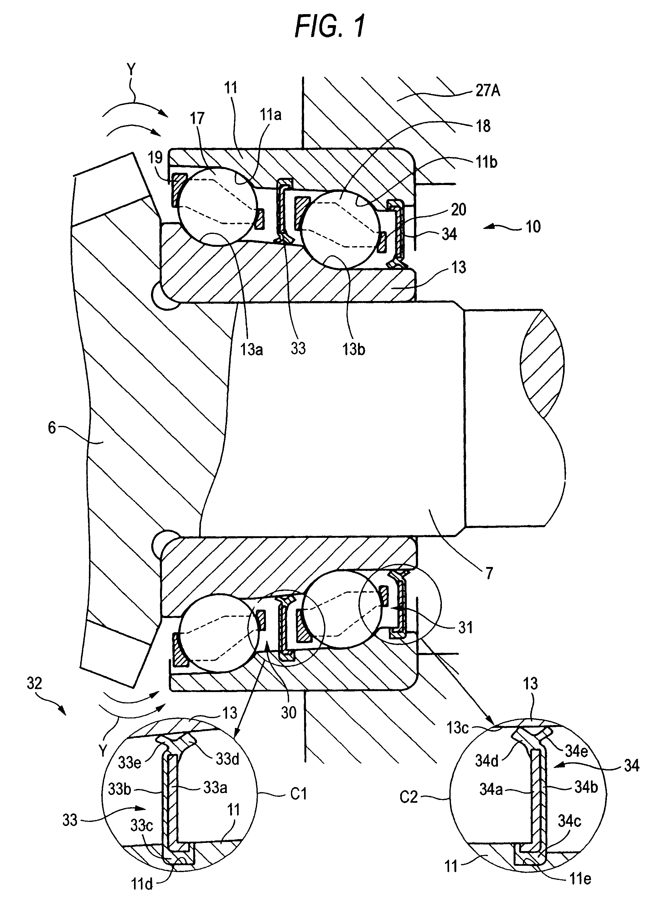
[0071]A second embodiment of a bearing device of the invention will be described with reference to FIG. 2.

[0072]In this second embodiment, that side of a first ball row 17 facing a pinion gear 6 is exposed outwardly of a pinion gear-side end surface 11c of an outer ring 11 so that oil spattered by the rotating pinion gear 6 can deposit on the first ball row 17. The other construction is similar to that of the first embodiment.

[0073]In the second embodiment, a second bearing internal space 31 is sealed by bearing seals 33 and 34, and therefore oil will not be supplied to the first ball row 17 from a smaller-diameter side of a double row rolling bearing 10.

[0074]In this case, as described above for the first embodiment, a first bearing internal space 30 is open to the interior 32 of a case, and also is disposed near to the pinion gear 6, and therefore oil spattered by the pinion gear 6 can deposit on bearing constituent elements (larger-diameter raceways 11a and 13a of inner and outer...

third embodiment

[0077]A method of assembling the bearing device of the second embodiment will be described with reference to FIGS. 3 to 5. FIG. 3 is a cross-sectional view showing a condition before an inner ring assembly is mounted on the outer ring, FIG. 4 is a cross-sectional view showing the process of mounting the inner ring assembly on the outer ring, and FIG. 5 is a cross-sectional view showing a condition after the inner ring assembly is mounted on the outer ring.

[0078]In this third embodiment, the inner ring 13, the first ball row 17 and a first cage 19 jointly form the inner ring assembly 40. Also, the outer ring 11, a second ball row 18, a second cage 20 and first and second bearing seals 33 and 34 jointly form an outer ring assembly 41.

[0079]This double row rolling bearing 10 is the double row rolling bearing of the second embodiment. As shown in FIG. 3, the outer ring assembly 41 is fixed to an inner peripheral surface of an annular wall 27A, and the inner ring assembly 40 is fitted on...


PUM


Abstract

In a bearing device, a double row rolling bearing for supporting a pinion gear-side portion of a pinion shaft on a case (annular wall) is formed by a tandem-type double row angular contact ball bearing. A first row of balls having a larger pitch circle diameter are disposed between inner and outer rings of the double row angular contact ball bearing at a region near to the pinion gear, and a second row of balls having a smaller pitch circle diameter are disposed between the inner and outer rings at a region remote from the pinion gear. A bearing internal space is divided into a first bearing internal space containing the first ball row and open toward the pinion gear and a second bearing internal space containing the second ball row and sealed by partition walls formed respectively by bearing seals, lubricating grease being sealed in the second bearing internal space.

Description

BACKGROUND OF THE INVENTION[0001]1. Field of the Invention[0002]This invention relates to a rolling bearing device for supporting a pinion shaft (hereinafter referred to as “bearing device”) for rotatably supporting two portions (that is, a pinion gear-side portion and a counter-pinion-gear-side portion) of a pinion shaft (incorporated in an automotive differential apparatus, a transfer apparatus for a four-wheel drive vehicle or the like) by rolling bearings.[0003]2. Related Art[0004]In an automotive differential apparatus and a transfer apparatus for a four-wheel drive vehicle, it has heretofore been proposed to use a bearing device, in which tapered roller bearings (serving as rolling bearings) are provided respectively at a pinion gear-side portion (one axial end portion) of a pinion shaft and a counter-pinion-gear-side portion (the other axial end portion) of the pinion shaft, and the pinion shaft is rotatably supported on an inner periphery surface of a case by the two tapered...

Claims


Application Information

Patent Timeline
Patent Type & Authority Patents(United States)
IPC IPC(8): F16C33/66F16C33/76F16C19/18F16C19/49F16C33/78F16H57/02F16H57/021
CPCF16C19/182F16C19/49F16C19/548F16C33/6603F16C33/6681F16C33/7853F16H57/037F16H57/0483F16C2240/80F16H57/021F16H57/0471F16H2048/423F16C2361/61
Inventor KAWAGUCHI, TOSHIHIRO
Owner JTEKT CORP
Why Eureka
Try Eureka