
Lever type connector

a technology of lever connector and connector, which is applied in the direction of coupling device connection, coupling parts engagement/disengagement, incorrect coupling prevention, etc., can solve the problems of deviation from each other, and achieve the effect of preventing the separation of the lever, and keeping the lever not to be separated

Active Publication Date: 2010-10-12
YAZAKI CORP
View PDF8 Cites 6 Cited by
  • Summary
  • Abstract
  • Description
  • Claims
  • Application Information

AI Technical Summary

Benefits of technology

This design effectively prevents lever separation and deviation, improving the reliability and ease of assembly by ensuring secure engagement of the lever with the connector housing, even under external forces, and allowing for compact structure and efficient fitting operations.

Problems solved by technology

In this case, a swing fulcrum close to the lever and a swing fulcrum close to the connector housing fitted to each other may deviate from each other, by applying unexpected excessive external force.

Method used


Image

  • Lever type connector
  • Lever type connector
  • Lever type connector

Examples


Embodiment Construction

[0032]Hereinafter, an embodiment of the invention will be described with reference to the drawings.

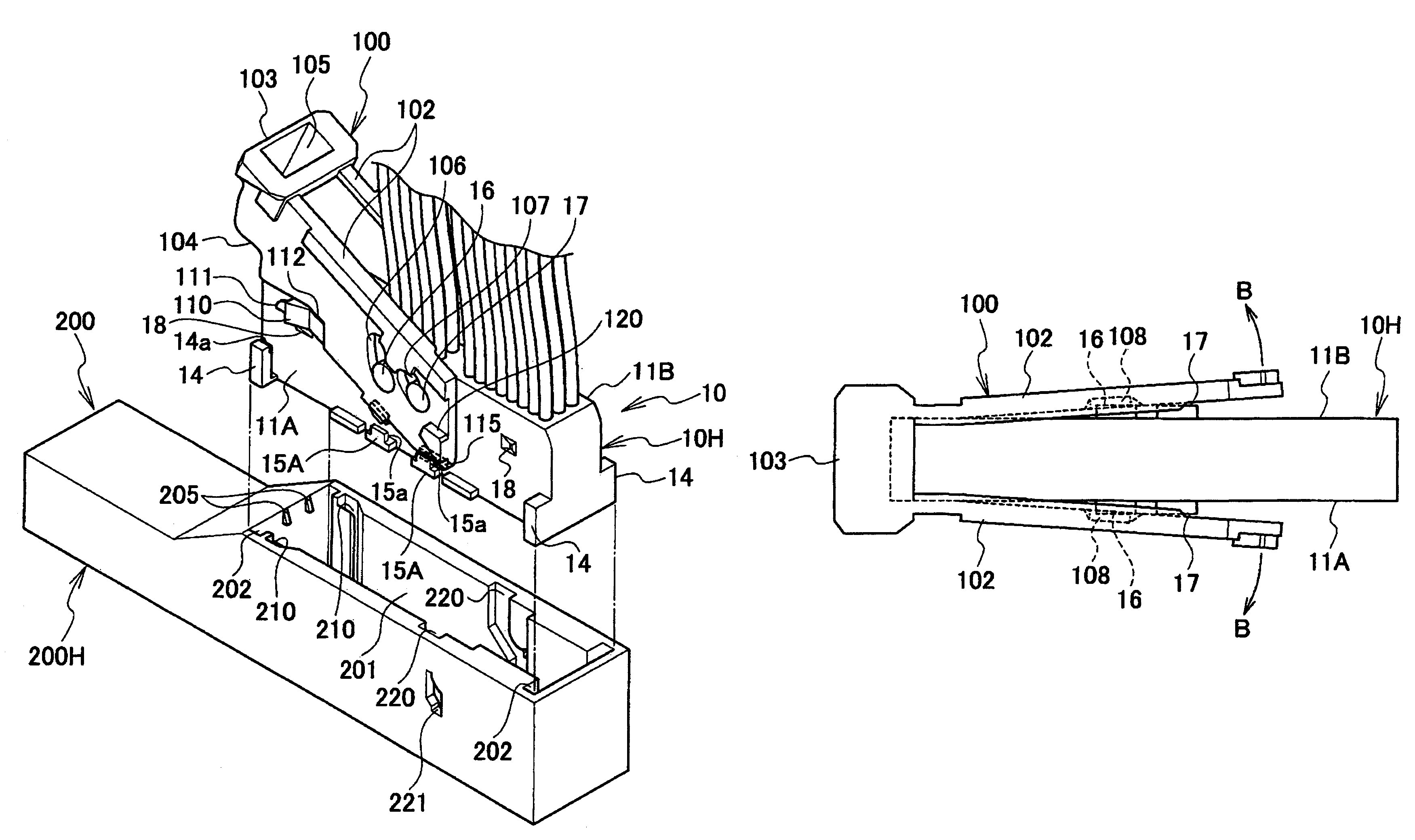
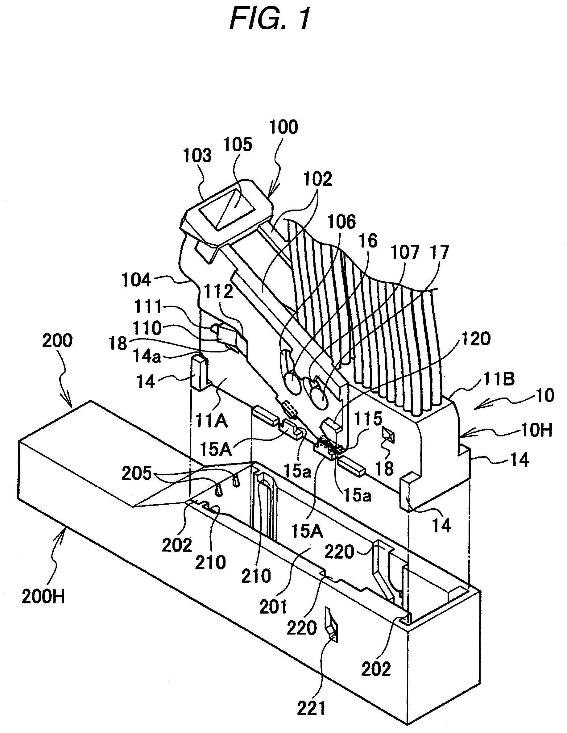
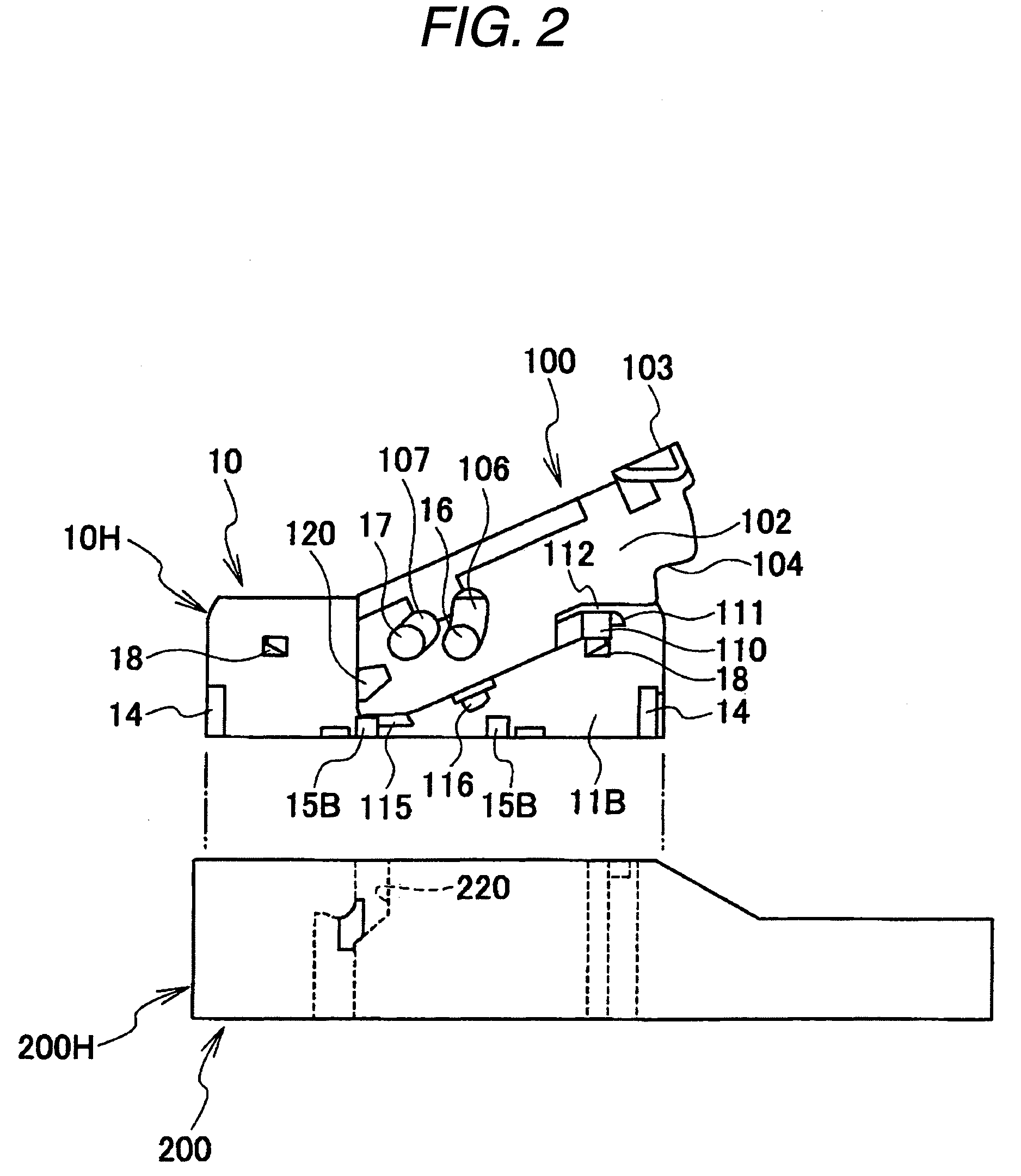
[0033]FIG. 1 is a perspective view illustrating a state before fitting of a lever type connector according to an embodiment, FIG. 2 is a side view as viewed from the side opposite to FIG. 1, FIG. 3 is a perspective view as viewed from the bottom of a lever, FIG. 4 is a transverse-sectional view illustrating a part provided with a guide slope of the lever, FIG. 5 is a side view illustrating a first step of mounting the lever on a male connector housing, FIG. 6 is a side view illustrating a state of slightly swinging the lever from the state shown in FIG. 5, FIG. 7 is a schematic plan view as viewed from the top in the state shown in FIG. 6, FIG. 8 is a side view illustrating a state before swinging the lever to a temporary locking position in the state of mounting the lever on the male connector, FIG. 9 is a side view as viewed from the side opposite to FIG. 8, FIG. 10 is a side view il...


PUM


Abstract

Provided is a lever type connector for fitting connectors by swinging a lever 100, in which protrusions 115 and 116 are provided on an outer peripheral portion of the one end side of the lever side plate 102, a reception portion 15A for preventing the lever side plate from opening outward by engaging with the protrusions provided on the outer peripheral portion of the lever side plate in a male connector housing 10H for mounting the lever, and the protrusions 115 and 116 and the reception portion 15A are provided to engage with each other when the lever mounted on at least the male connector housing is set to a temporary locking position before connector fitting.

Description

BACKGROUND OF THE INVENTION[0001]1. Field of the invention[0002]The invention relates to a lever type connector capable of fitting or separating female and male connector housings with little force by a swing operation of a lever.[0003]2. Description of the Related Art[0004]A lever type connector is provided with a lever that is swingably mounted on one connector housing of a pair of connector housings fitted to each other, and help both connector housings to be fitted and separated by an operation of a cap mechanism provided between the lever and the other connector housing, by a swing operation of the lever.[0005]For example, a lever of a lever type connector described in Patent Document 1 has a swing fulcrum portion (swing hole) fitted to a swing fulcrum portion close to a connector housing on one end side of a pair of left and right lever side plates, and has a substantially U shape having an operation portion connecting both lever side plates to each other on the other side of ...

Claims


Application Information

Patent Timeline
Patent Type & Authority Patents(United States)
IPC IPC(8): H01R13/62
CPCH01R13/62938H01R13/62955
Inventor MATSUMURA, KAORUTSURUTA, AKIHIRO
Owner YAZAKI CORP
Learn More