Shielded electrical connector with a spring arrangement

a technology of shielding and electrical connectors, applied in the direction of coupling protective earth/shielding arrangements, electrical devices, coupling device connections, etc., to achieve the effect of reducing performance degradation over tim

Inactive Publication Date: 2010-10-12
FUSION COMPONENTS
View PDF13 Cites 136 Cited by
  • Summary
  • Abstract
  • Description
  • Claims
  • Application Information

AI Technical Summary

Benefits of technology

[0011]a spring arrangement coupled to the shielding arrangement for resiliently urging the shielding of the cable against the annular surface of the shielding arrangement to thereby provide a reliable electrical connection between the cable and the shielding arrangement.
[0012]The invention thus provides a shielded connector in which an electrical and / or mechanical connection with the shielding of a cable may be maintained by a spring arrangement. In this way, the need for special tools may be avoided. Moreover, the nature of the spring arrangement may be such that a resilient force is constantly maintained for the service life of the connector, thereby minimising performance degradation over time.
[0017]The collar may defines a frusto-conical surface arranged to engage with a frusto-conical surface of the shielding arrangement. Additionally, the collar may defines an annular projection arranged to engage with (i.e. be received by) the annular groove of the shielding arrangement. These features may also provide for good electrical connection between the shielding arrangement and the shielding of the cable.

Problems solved by technology

Moreover, the nature of the spring arrangement may be such that a resilient force is constantly maintained for the service life of the connector, thereby minimising performance degradation over time.

Method used


Image

  • Shielded electrical connector with a spring arrangement
  • Shielded electrical connector with a spring arrangement
  • Shielded electrical connector with a spring arrangement

Examples


Embodiment Construction

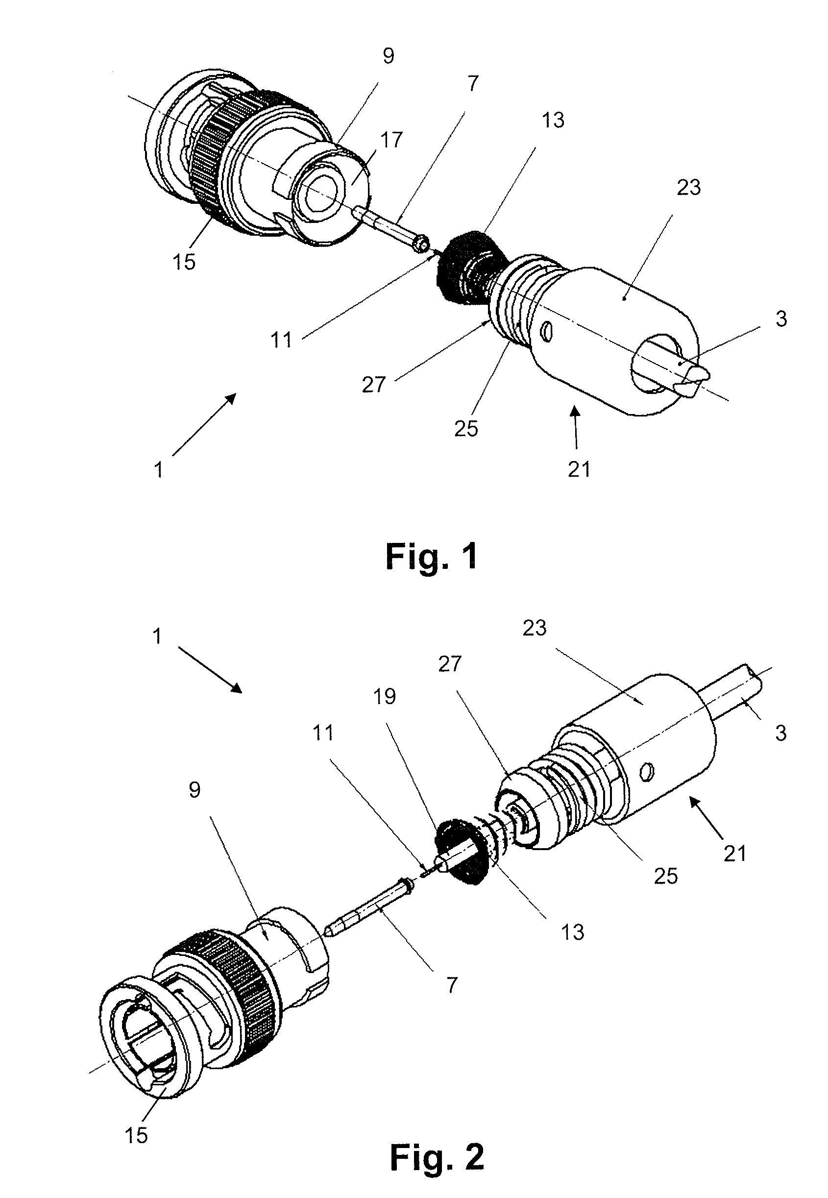
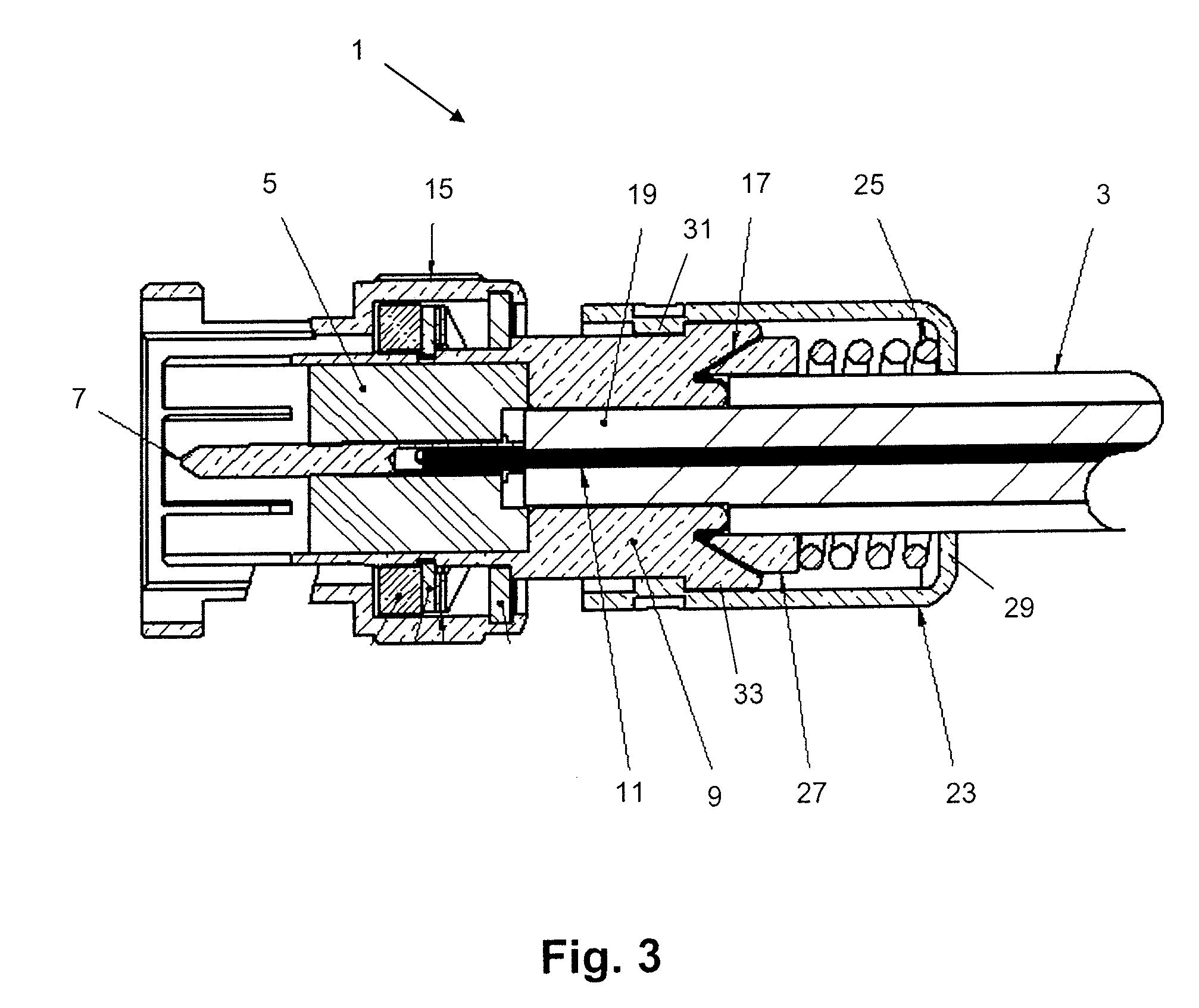
[0028]The invention provides a connector for a shielded electrical cable having at least one insulated central conductor surrounded by conductive shielding. The connector comprises a dielectric spacing element for receiving the at least one central conductor of the cable, and a conductive shielding arrangement provided around the spacing element and having a first end which defines an annular surface for contacting the shielding of the cable. The connector also comprises a spring arrangement coupled to the shielding arrangement for resiliently urging the shielding of the cable against the annular surface of the shielding arrangement to thereby provide a reliable electrical connection between the cable and the shielding arrangement.

[0029]Referring to FIGS. 1, 2 and 3, a shielded connector 1 for a shielded electrical cable 3 comprises a substantially cylindrical dielectric spacing element 5 formed of a plastics material having good electrical insulating properties. The spacing element...


PUM


Abstract

A connector for a shielded electrical cable. The cable has at least one insulated central conductor surrounded by conductive shielding. The connector comprises a dielectric spacing element for receiving the at least one central conductor of the cable and a conductive shielding arrangement provided around the spacing element and having a first end which defines an annular surface for contacting the shielding of the cable. The connector further comprises a spring arrangement coupled to the shielding arrangement for resiliently urging the shielding of the cable against the annular surface of the shielding arrangement to thereby provide a reliable electrical connection between the cable and the shielding arrangement.

Description

FIELD OF THE INVENTION[0001]This invention relates to a shielded electrical connector. More particularly, this invention relates to a shielded electrical connector having a means for providing an electrical grounding connection.BACKGROUND OF THE INVENTION[0002]Shielded electrical connectors are well known. These connectors are used for coupling shielded cables, which are electrical cables in which at least one insulated inner conductor is enclosed by a conductive shielding layer. Where there is a single insulated inner conductor, shielded cables are known as coaxial cables.[0003]Shielded cables are typically used in applications where it is desired to minimise the effect of electrical noise on signals which are being carried in the cables or to reduce the electromagnetic radiation emitted by the cables. The former is particularly important for cables carrying high bandwidth signals which are particularly susceptible to noise. The latter is important for cables carrying high voltages...

Claims


Application Information

Patent Timeline
Patent Type & Authority Patents(United States)
IPC IPC(8): H01R9/03
CPCH01R9/0527H01R4/4863H01R9/05H01R13/658H01R13/65917
Inventor GRAY, IAN JAMES STAFFORD
Owner FUSION COMPONENTS
Why Eureka
Try Eureka