
Interactive MPLS traffic engineering

a traffic engineering and interactive technology, applied in the field of traffic engineering, can solve the problems of few, if any, of the ancillary changes that are actually implemented, the actual optimization of the network's performance becomes a daunting and sometimes infeasible or impractical task, and the implementation is infeasible or impractical, so as to facilitate the analysis and selection

Active Publication Date: 2010-10-12
RIVERBED TECH LLC
View PDF6 Cites 15 Cited by
  • Summary
  • Abstract
  • Description
  • Claims
  • Application Information

AI Technical Summary

Benefits of technology

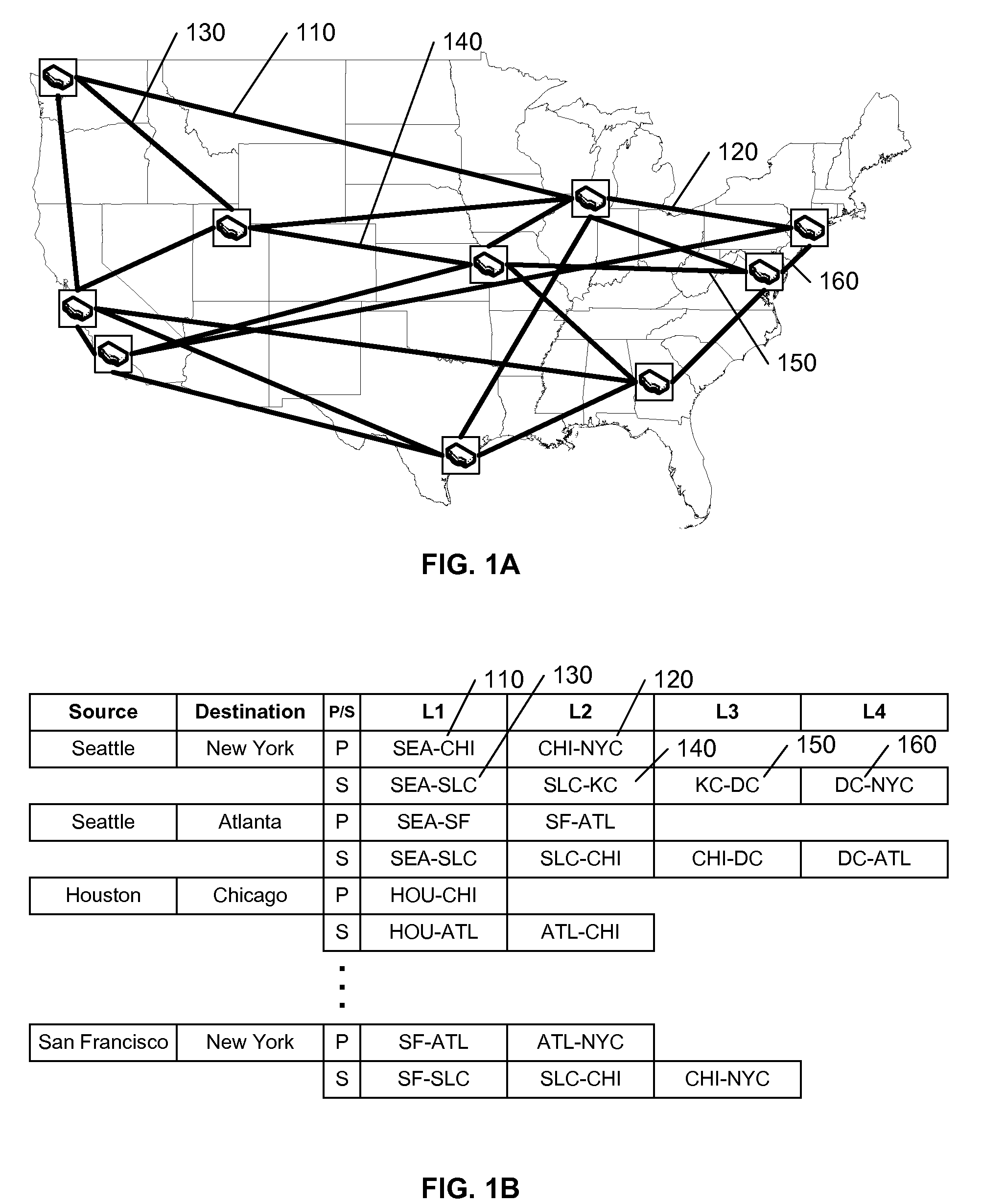
[0003]Traffic engineering generally includes the tasks of predicting the behavior of communications networks, and modifying the behavior as required to provide an efficient and effective use of resources throughout the network. Traffic Engineering includes the process of creating ‘virtual circuits’ between source and destination nodes in order to make efficient use of network resources, to satisfy routing constraints for the circuits, and to improve network survivability. In the field of Multi-Protocol Label Switching, for example, traffic engineering includes determining primary and secondary routes for Label Switched Paths (LSPs).
[0010]It would be advantageous to provide an interactive system that allows a network manager or traffic engineer to address one or more specified routes for customized traffic engineering optimization, based on potential changes to the specified routes. It would be advantageous to allow the user to define the constraints that are to be used by the system in identifying the potential changes to the specified routes. It would be also be advantageous to record any changes selected by the user for implementation, and to generate the data necessary to reconfigure the network to effect the selected change(s).
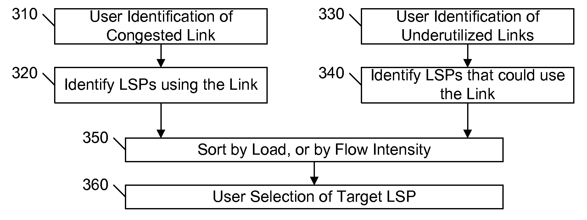
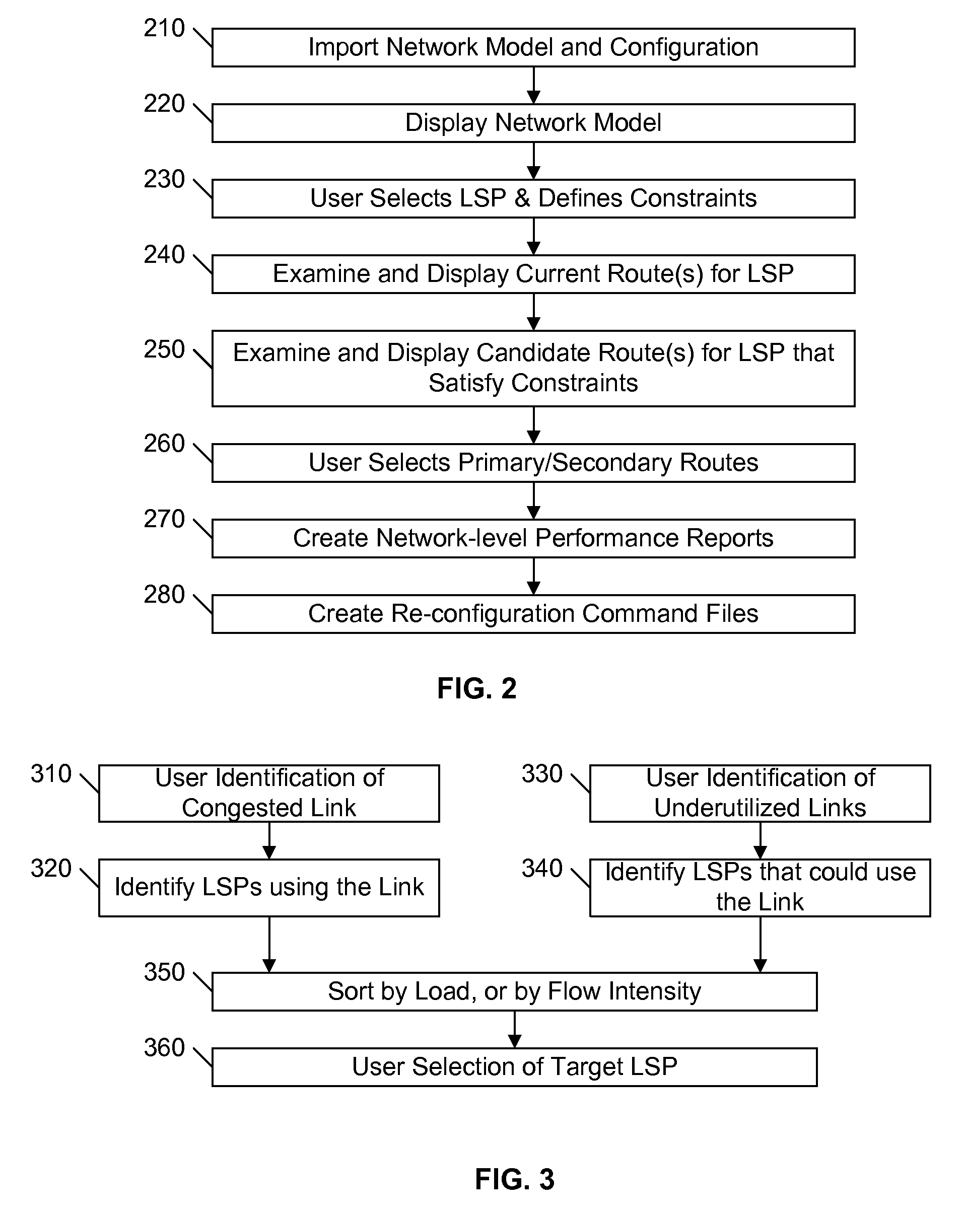
[0011]These advantages, and others, can be realized by an interactive system and method that automates the control and management of routing changes that are focused on specific routes or particular network hot spots. Based on the premise that the user is aware of a particular problem that needs to be solved, the system leads the user through an end-to-end process from the identification of the problem to the generation of configuration instructions for effecting a selected solution. A graphic user interface provides a visualization of the current routing and alternative routings, to facilitate the analysis and selection of an improved routing, if any. Throughout the process, the effect of each proposed routing change on the overall network performance is monitored, so that the selection of a preferred solution can be made in the appropriate context, and globally sub-optimal solutions can be avoided.

Problems solved by technology

As networks become more and more complex, with dynamic changes occurring regularly, the actual optimization of a network's performance becomes a daunting and sometimes infeasible or impractical task.
Often, due to the risks of introducing unanticipated problems with each change, and the well recognized maxim of “if it isn't broken, don't ‘fix’ it”, few, if any, of the ancillary changes are actually implemented.
Unfortunately, the resultant preferred or optimal solution often has little correspondence to the current configuration of the network, and the number of changes required to implement the proposed solution makes such an implementation infeasible or impractical.
Conceptually, these processes are well suited for ‘strategic’ or ‘global’ traffic engineering, but are poorly suited for ‘tactical’ or ‘operational’ traffic engineering.
Because of the multiple dependencies among routes of a network, however, the ad-hoc improvement of one route may introduce problems and / or cause degraded performance on other routes, often with significant unforeseen consequences.
In many cases, the degraded performance occurs over the course of multiple ad-hoc changes, and the identification of the particular change(s) that needs to be undone to restore the network to its past performance capabilities is, at best, challenging.

Method used


Image

  • Interactive MPLS traffic engineering
  • Interactive MPLS traffic engineering
  • Interactive MPLS traffic engineering

Examples


Embodiment Construction

[0020]In the following description, for purposes of explanation rather than limitation, specific details are set forth such as the particular architecture, interfaces, techniques, etc., in order to provide a thorough understanding of the concepts of the invention. However, it will be apparent to those skilled in the art that the present invention may be practiced in other embodiments, which depart from these specific details. In like manner, the text of this description is directed to the example embodiments as illustrated in the Figures, and is not intended to limit the claimed invention beyond the limits expressly included in the claims. For purposes of simplicity and clarity, detailed descriptions of well-known devices, circuits, and methods are omitted so as not to obscure the description of the present invention with unnecessary detail.

[0021]FIG. 1A illustrates an example network diagram that shows links 110, 120, etc. between nodes that are located at various geographic locati...


PUM


Abstract

An interactive system and method automates the control and management of routing changes that are focused on specific routes or particular network hot spots. Based on the premise that the user is aware of a particular problem that needs to be solved, the system leads the user through an end-to-end process from the identification of the problem to the generation of configuration instructions for effecting a selected solution. A graphic user interface provides a visualization of the current routing and alternative routings, to facilitate the analysis and selection of an improved routing, if any. Throughout the process, the effect of each proposed routing change on the overall network performance is determined, so that the selection of a preferred solution can be made in the appropriate context, and globally sub-optimal solutions can be avoided.

Description

[0001]This application claims the benefit of U.S. Provisional Patent Application 60 / 912,713, filed 19 Apr. 2007.BACKGROUND AND SUMMARY OF THE INVENTION[0002]This invention relates to the field of traffic engineering, and in particular to the interactive maintenance and enhancement of routes for virtual circuits, such as Label-Switched Paths (LSPs), subject to routing and other network traffic constraints.[0003]Traffic engineering generally includes the tasks of predicting the behavior of communications networks, and modifying the behavior as required to provide an efficient and effective use of resources throughout the network. Traffic Engineering includes the process of creating ‘virtual circuits’ between source and destination nodes in order to make efficient use of network resources, to satisfy routing constraints for the circuits, and to improve network survivability. In the field of Multi-Protocol Label Switching, for example, traffic engineering includes determining primary an...

Claims


Application Information

Patent Timeline
Patent Type & Authority Patents(United States)
IPC IPC(8): H04L12/24H04J3/14
CPCH04L41/0803H04L41/0886H04L41/12H04L41/145H04L41/22H04L41/5009
Inventor BOLT, GORDONERNST, MICHAELSYKES, EDWARD A.
Owner RIVERBED TECH LLC
Learn More