Supercharge Your Innovation With Domain-Expert AI Agents!

Power management system for a communication device

a communication device and power management technology, applied in the field of power management systems for communication devices, can solve the problems of limited capacity of vehicle batteries and battery death, and achieve the effect of reducing the power consumption of communication devices and reducing discharg

Inactive Publication Date: 2010-10-12
AISIN AW CO LTD
View PDF53 Cites 15 Cited by
  • Summary
  • Abstract
  • Description
  • Claims
  • Application Information

AI Technical Summary

Benefits of technology

"The invention provides a power management system for a communication device in a vehicle. The system includes an accessory-signal generating device, a communication device, and a power management device. The power management device controls the flow of electric power to the communication device when no accessory-signal is generated, reducing the power consumption of the communication device and minimizing the discharge of the battery. This system helps to manage the power supply for the communication device and ensures that the vehicle battery is not overused. Additionally, the invention provides a startup management device for activating the communication device upon receipt of startup-signals from another device."

Problems solved by technology

However, the capacity of the vehicle battery is limited and there is a possibility that the battery will die if the on-board apparatus is only powered by a vehicle battery.
This is a problem with the conventional system.

Method used


Image

  • Power management system for a communication device
  • Power management system for a communication device
  • Power management system for a communication device

Examples


first embodiment

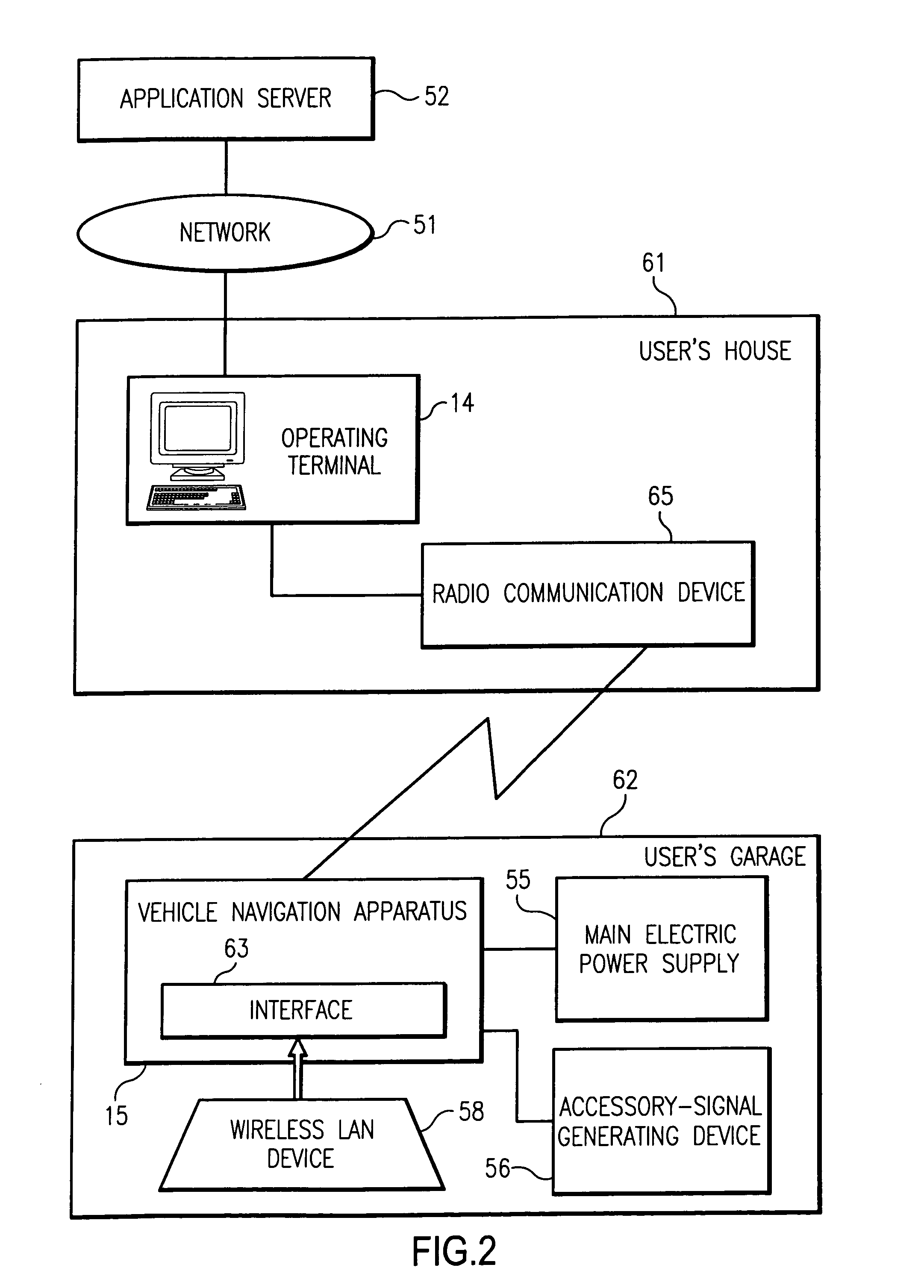
[0018]FIG. 2 illustrates the composition of a communication system wherein a vehicle navigation apparatus and an operating terminal are communicated with each other according to the invention.

[0019]FIG. 2 shows a vehicle navigation apparatus 15 aboard a passenger vehicle, a truck, a bus, or a motorcycle. A wireless LAN (Local Area Network) device 58 is coupled to an interface 63 in the vehicle navigation apparatus 15. The wireless LAN device 58 is, for example, a wireless LAN card. The interface 63 is, for example, a card slot to which the wireless LAN card is loaded. The wireless LAN device 58 may be preliminarily built in the vehicle navigation apparatus. In the interest of the simplicity, the detailed composition of the vehicle is omitted from FIG. 2. However, there is shown a vehicle battery serving as a main electric power supply 55. The main electric power supply 55 is coupled to the vehicle navigation apparatus 15, so as to supply the vehicle navigation apparatus 15 with elec...

second embodiment

[0101]FIG. 7 illustrates the composition of a power management system for a communication device according to the present invention.

[0102]The power management system for the communication device according to the second embodiment includes; a wireless LAN device 58, serving as a first communication device, and a specific low-power radio communication device 57, serving as a second communication device. The specific low-power radio communication device 57 is the second communication device that receives certain signals from a specific low-power radio transmitter, such as a remote control unit, to unlock doors of the vehicle, to start an engine of the vehicle, or to set a warning system installed in the vehicle. Each of the power output line 42b, the accessory-signal output line 43b, and the startup-signal output line 44b are connected to the wireless LAN device 58, in order that the wireless LAN device 58 can receive in-communication signals sent from the specific low-power radio comm...


PUM


Abstract

A power management system for a communication device, including an accessory-signal generating device; the communication device; and a power management device for supplying electric power to the communication device if the accessory-signal generating device is not generating accessory signals and the communication device is in a communication-ready state.

Description

INCORPORATION BY REFERENCE[0001]This application is a continuation of U.S. application Ser. No. 10 / 633,684, filed Aug. 5, 2003, which claims priority of the disclosures of Japanese Patent Application No. 2002-232656 filed Aug. 9, 2002, and Japanese Patent Application No. 2002-232699 filed Aug. 9, 2002. The disclosures of these applications, including the specifications, drawings and claims, are incorporated herein by reference in their entirety.BACKGROUND OF THE INVENTION[0002]1. Field of Invention[0003]The invention relates to a power management system for a communication device.[0004]2. Description of Related Art[0005]There are conventional on-board navigation systems, wherein route guidance data is preliminarily transmitted to the on-board navigation system prior to a user's departure and the user is provided with route guidance based on the transmitted route guidance data at his or her departure (please refer to Japanese patent laid-open H6-243395 and H9-189566.) In this convent...

Claims


Application Information

Patent Timeline
Patent Type & Authority Patents(United States)
IPC IPC(8): G06F1/26G06F1/32G08G1/00H04B1/16H04L12/10H04L12/28H04M17/00H04W12/06H04W52/02
CPCH04W52/028Y02D30/70G06F1/26
Inventor NAITOU, MITSUHIROYAMADA, KUNIHIROOGAWA, SATOSHI
Owner AISIN AW CO LTD
Features
  • R&D
  • Intellectual Property
  • Life Sciences
  • Materials
  • Tech Scout
  • Unparalleled Data Quality
  • Higher Quality Content
  • 60% Fewer Hallucinations
Learn More