Composite mandrel

a composite material and mandrel technology, applied in the field of mandrels, can solve the problems of thermal instability, non-uniformity of the composite product formed thereon,

Inactive Publication Date: 2010-10-19
A&P TECH
View PDF56 Cites 12 Cited by
  • Summary
  • Abstract
  • Description
  • Claims
  • Application Information

AI Technical Summary

Benefits of technology

[0017]Embodiments of the composite mandrel construction, taught herein, impart higher stiffness and lower weight than prior art mandrel constructions, thereby facilitating automatic and / or semi-automatic application of wrinkle-free, or undulation-free, composite material layers in the composite preform as it is applied, and / or cured upon the mandrel.
[0018]A plurality of composite mandrels, as taught herein, may be joined together to create more complex shapes, such as axially tandem straight, circular, or non-circular profiles along the longitudinal axis of the mandrels, thereby facilitating the manufacture of multiple composite preforms in a single manufacturing operation.
[0020]Thus, one advantage of one of the embodiments of the invention is to provide a dimensionally-stable composite mandrel for producing near-net shape composite preforms thereon that overcome one or more of the shortcomings of the prior art.
[0021]It is a further advantage of one of the embodiments of the present invention to provide a composite mandrel for producing near-net shape composite preforms thereon, whereby composite fibers may be braided or otherwise applied to be later infused with a binding agent in a mold and formed into a final composite product using a plurality of composite manufacturing methods.

Problems solved by technology

In the manufacture of a curved composite preform product, the prior art mandrels made of wood often exhibit an instability that results in non-uniformity of the composite product being formed thereon.
While metallic mandrels may tend to solve the wooden mandrels' instability, they are nevertheless subject to thermal instability caused by ambient temperature changes.

Method used


Image

  • Composite mandrel
  • Composite mandrel
  • Composite mandrel

Examples


Embodiment Construction

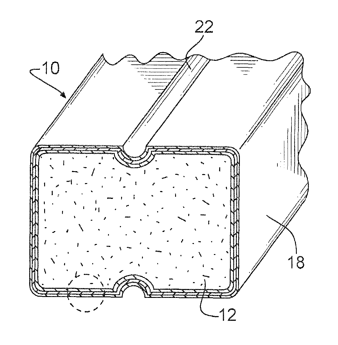
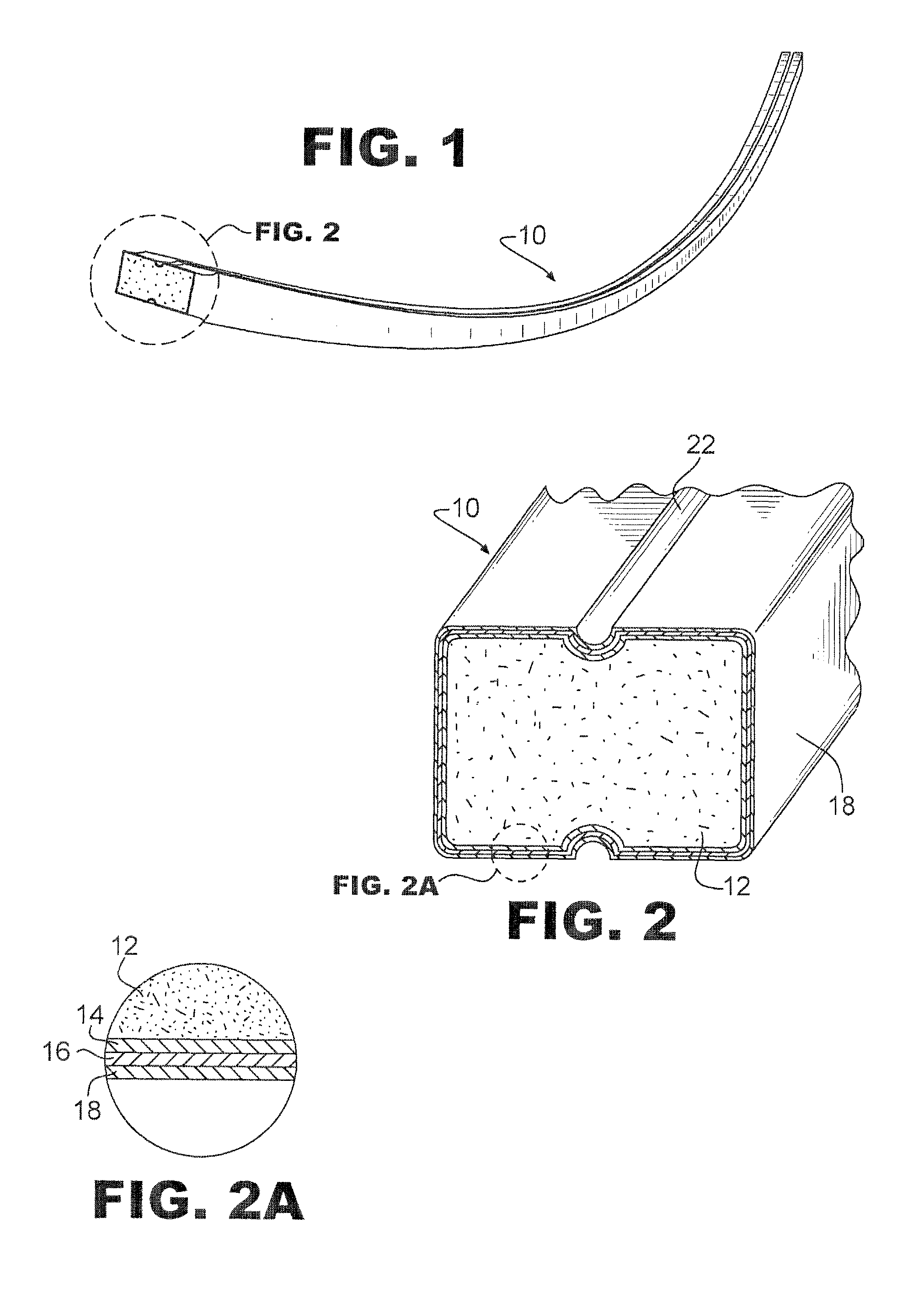
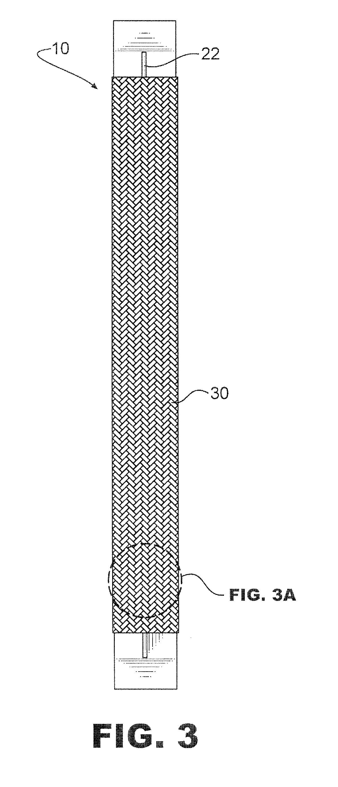
[0022]FIG. 1 generally illustrates a mandrel 10, having a curved axial profile, embodying an embodiment of the present invention. Mandrel 10 may also embody a longitudinally straight profile or any of a plurality of axial profiles. Although the lateral cross-section of mandrel 10 is illustrated as generally having a rectangular cross-section, mandrel 10 may alternately embody any of a plurality of desired cross-sectional profiles, or may include a varying cross-section along its longitudinal length. For example, the mandrel illustrated in FIG. 5 is but one of a multitude of cross-sectional profiles that can be utilized. As such, any shape, size, and curvature of mandrel is contemplated for use in the different embodiments of the present invention.

[0023]Referring now to FIGS. 2 and 2A, mandrel 10 may comprise a high density, polyurethane foam core 12 having a first over-wrapped layer 14 of carbon fiber-reinforced resinous material, an optional second over-wrapped layer 16 of carbon f...


PUM

PropertyMeasurementUnit
resilientaaaaaaaaaa
densityaaaaaaaaaa
shapeaaaaaaaaaa

Abstract

A mandrel for use as a substrate in the manufacture of woven or braided articles may comprise an inner core of foam; at least a first intermediate layer of carbon fiber-reinforced resin; and an outer layer of glass fiber-reinforced resin. The foam core may comprise a high density, closed cell polyurethane foam that is formed of a desired size and shape. The fibers in the intermediate layer and outer layer may be, for example, chopped fibers, continuous longitudinally aligned fibers, circumferentially wound fibers, obliquely aligned fibers, or the fibers may have a woven or braided pattern. Multiple mandrel may be joined together to form complex mandrel shapes such as curves, ovals, and circles.

Description

[0001]This application claims the benefit of U.S. provisional patent application 60 / 789,031, entitled “Composite Mandrel” and filed Apr. 4, 2006, which is hereby incorporated herein by reference.TECHNICAL FIELD[0002]The present invention relates to an improved mandrel for producing near-net shape composite preforms thereon.BACKGROUND OF THE INVENTION[0003]It is known in the art of manufacturing articles comprising composite materials to first form a mandrel upon which the composite product is preformed. In the prior art, such mandrels are typically manufactured from solid wood, laminated wood, and / or metallic materials.[0004]In the manufacture of a curved composite preform product, the prior art mandrels made of wood often exhibit an instability that results in non-uniformity of the composite product being formed thereon. While metallic mandrels may tend to solve the wooden mandrels' instability, they are nevertheless subject to thermal instability caused by ambient temperature chan...

Claims


Application Information

Patent Timeline
Patent Type & Authority Patents(United States)
IPC IPC(8): B29C33/40B29C70/34
CPCB29C53/82B29C70/446B29C70/865B29C33/40B29B11/16Y10T156/10B29C63/18B29K2105/04B29K2105/046B29K2105/06B29K2105/0827B29K2105/0845B29K2707/04B29L2031/709B29K2221/00
Inventor STENARD, STEVEN
Owner A&P TECH
Why Eureka
Try Eureka