Fuel cell apparatus having fuel cell stack and controller, and method of manufacturing same

a fuel cell and controller technology, applied in the manufacture of final products, cell components, cell component details, etc., can solve the problems of reactant depletion, short-circuit current decrease, uneven power generation characteristics, etc., and achieve the effect of high power generation density

Inactive Publication Date: 2010-10-19
CANON KK
View PDF4 Cites 0 Cited by
  • Summary
  • Abstract
  • Description
  • Claims
  • Application Information

AI Technical Summary

Benefits of technology

[0012]The present invention has been accomplished to solve the foregoing problems in the conventional technologies, and provides a fuel cell apparatus including a fuel cell stack of a plurality of fuel cells electrically connected in series with each other and a control means for controlling the fuel cell stack with a part of the electric power generated by the fuel cell stack. In this fuel cell apparatus, the power generation characteristics of each fuel cell can be sufficiently utilized and high power generation density can be achieved even if the short-circuit current of each of the fuel cells constituting the fuel cell stack is different from that of each other.
[0022]According to the present invention, by connecting the fuel cells in series, a large electromotive force can be obtained and, simultaneously, the power generation characteristics of each fuel cell can be sufficiently utilized. Consequently, the fuel cell apparatus having high power generation density can be provided.

Problems solved by technology

For example, in Journal of Power Sources, 2002, 112: 410-418, F. B. Prinz, et al. have reported that unevenness in power generation characteristics occurs in a planar fuel cell stack.
The causes are not clear, but it is pointed out that the short-circuit current decreases in the fuel cells arranged at the downstream of the oxidant or fuel and that there are some problems of pressure loss, reactant depletion, and moisture control.
If the fuel cell stack having such unevenness generates power at a level higher than a short-circuit current of any one of the fuel cells, the current may flow in the reverse direction in that fuel cell, which will deteriorate the power generation characteristics of the fuel cell.
Therefore, the power generation characteristics of each fuel cell cannot be sufficiently utilized.
Furthermore, since a part of the output power from the fuel cell stack is supplied to the control means, power generation density of the fuel cell apparatus decreases, which is a problem.

Method used


Image

  • Fuel cell apparatus having fuel cell stack and controller, and method of manufacturing same
  • Fuel cell apparatus having fuel cell stack and controller, and method of manufacturing same
  • Fuel cell apparatus having fuel cell stack and controller, and method of manufacturing same

Examples


first embodiment

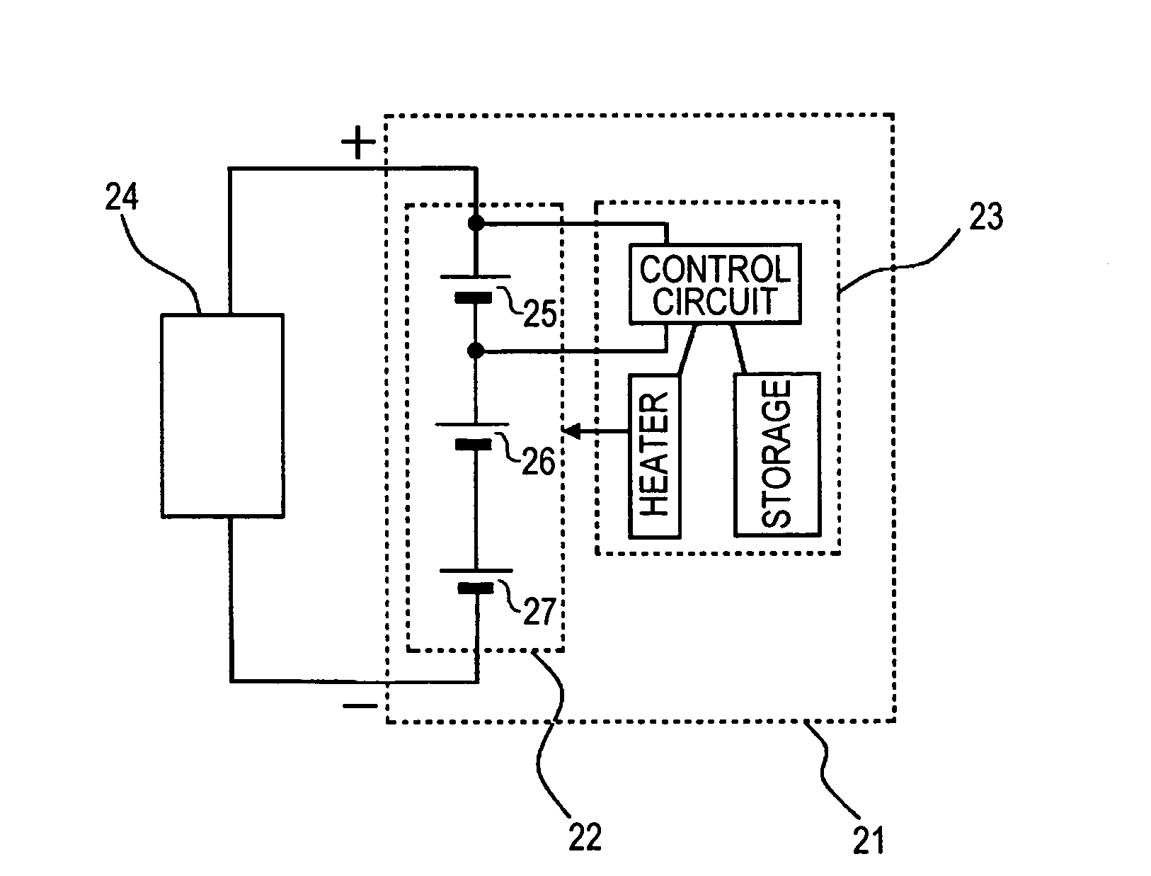
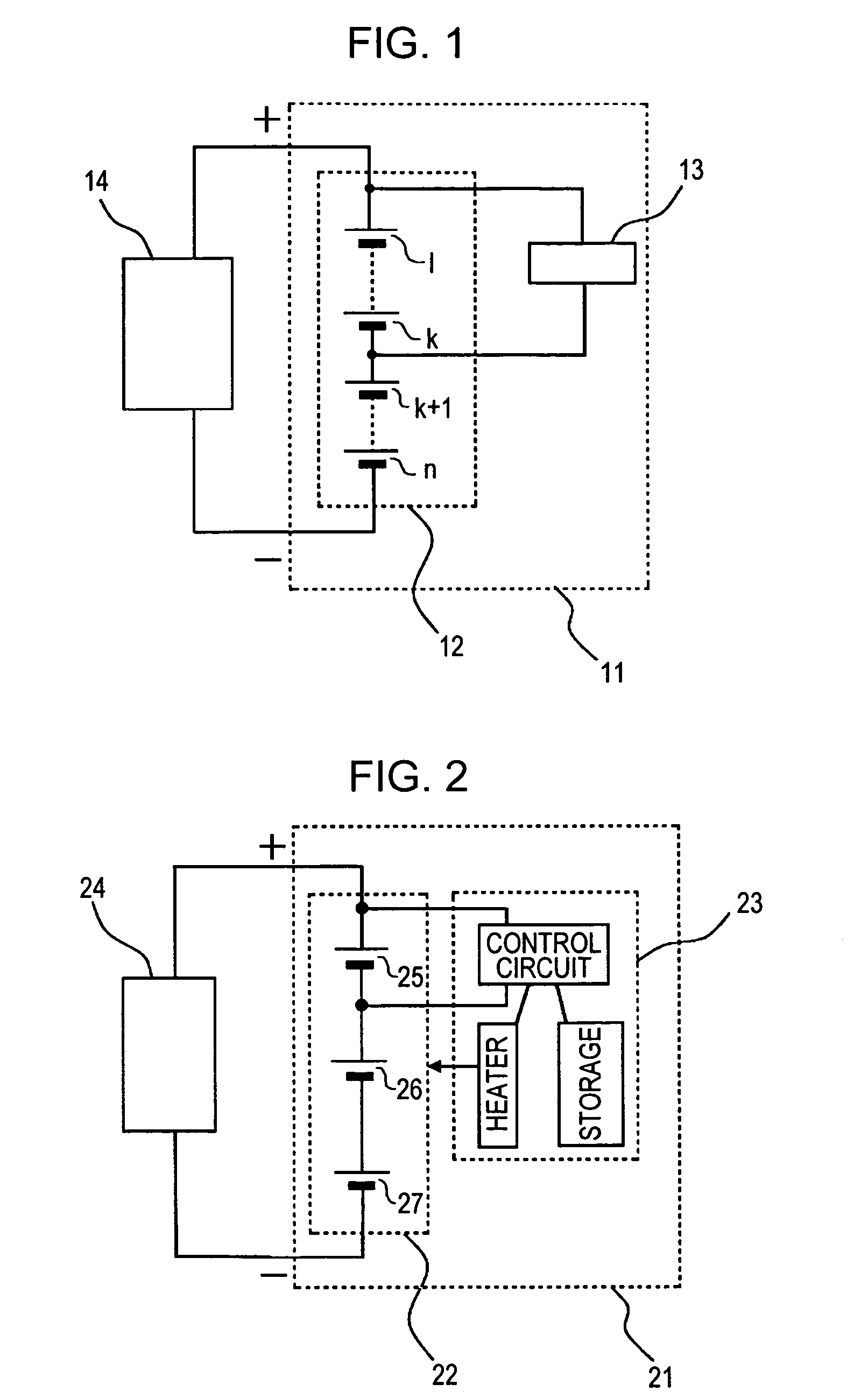
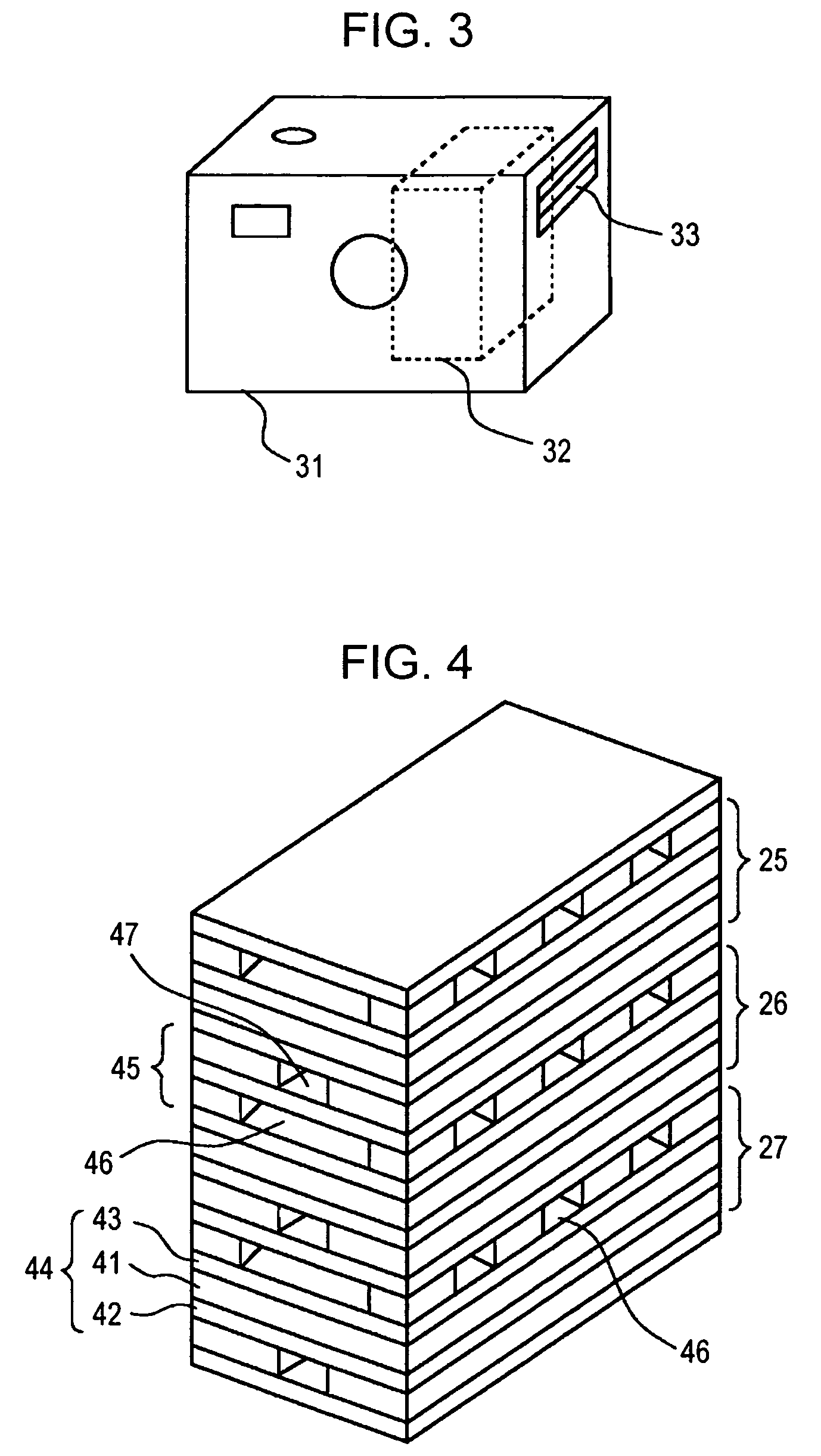
[0045]FIG. 2 shows a fuel cell apparatus 21 according to a first embodiment of the present invention. A reference number 22 is a fuel cell stack, a reference number 23 is a control means, and a reference number 24 is an electric device driven by the fuel cell apparatus. The fuel cell apparatus is installed in a housing of an electric device 31 shown in FIG. 3. A reference number 32 is a position where the fuel cell stack is arranged, and a reference number 33 is an air hole provided to the housing of the electric device.

[0046]FIG. 4 shows a fuel cell stack used in this embodiment. An electrolyte electrode assembly 44 includes an electrolyte membrane 41, a fuel electrode 42 on one face of the electrolyte membrane 41, and an oxidizer electrode 43 on another face of the electrolyte membrane 41. The electrolyte electrode assemblies are stacked so that the fuel electrode of one electrolyte electrode assembly faces the oxidizer electrode of another electrolyte electrode assembly adjacent ...

second embodiment

[0051]This embodiment relates to a fuel cell apparatus using a planar fuel cell stack. FIG. 6 is a schematic view of the fuel cell apparatus. A reference number 62 is a fuel cell stack, and a reference number 64 is an electric device driven by the fuel cell apparatus. This fuel cell apparatus utilizes oxygen and hydrogen supplied from the outside to generate electric power. A controller, such as control means 63, controls flow rates corresponding to output of the fuel cell stack and supplies oxygen and hydrogen to the fuel cell stack.

[0052]FIG. 7A shows cross-sectional views of each member of the planar fuel cell stack, and FIG. 7B shows the plan views of them. As shown in the drawings, fuel electrodes 72 and oxidizer electrodes 73 are formed on both faces of an electrolyte membrane 71, respectively. A fuel channel 74 for supplying hydrogen to the fuel electrodes is formed so as to be in contact with the fuel electrodes, and an oxidizer channel 75 for supplying oxygen to the oxidize...


PUM

PropertyMeasurementUnit
electromotive forceaaaaaaaaaa
electric poweraaaaaaaaaa
short-circuit currentaaaaaaaaaa

Abstract

A fuel cell apparatus includes a fuel cell stack of a plurality of fuel cells electrically connected in series with each other and a controller configured to control the fuel cell stack by using a part of electric power generated by the fuel cell stack. The controller is electrically connected in parallel with at least one of the fuel cells constituting the fuel cell stack, and short-circuit current of the at least one of the fuel cells is larger than that of at least one of the fuel cells constituting the fuel cell stack and not being electrically connected in parallel with the control means. With such a structure, a large electromotive force can be obtained by connecting the fuel cells in series and, simultaneously, the power generation characteristics of each fuel cell can be sufficiently utilized. Thus, the fuel cell apparatus having high power generation density can be provided.

Description

BACKGROUND OF THE INVENTION[0001]1. Field of the Invention[0002]The present invention relates to fuel cell apparatuses and a method of manufacturing fuel cell apparatuses.[0003]2. Description of the Related Art[0004]Energy per volume that fuel cell apparatuses can generate is likely to become several to ten times larger than that of conventional cells, and the fuel cell apparatuses allow small-sized electric devices such as cell-phones and notebook PCs to be continuously used for a long period of time by filling the fuel cell apparatuses with fuel. Thus, the fuel cell apparatuses are expected to be used.[0005]In a fuel cell, a fuel electrode having a catalyst and an oxidizer electrode having a catalyst are disposed on opposing faces of an electrolyte membrane, respectively. Fuel such as hydrogen gas is supplied to the fuel electrode, and an oxidant such as oxygen gas is supplied to the oxidizer electrode. These reactants react electrochemically through the electrolyte membrane there...

Claims


Application Information

Patent Timeline
Patent Type & Authority Patents(United States)
IPC IPC(8): H01M8/04H01M2/38
CPCH01M8/04H01M8/2475H01M8/1011H01M8/2415H01M8/242Y02P70/56H01M2250/30Y02E60/50Y02B90/18Y02B90/10Y02P70/50H01M8/2404H01M8/0263H01M8/2484H01M8/0258
Inventor MOGI, SATOSHISHIBATA, MASAAKI
Owner CANON KK
Why Eureka
Try Eureka