Program writing method of numerical controller, numerical controller and cutting machine controlled thereby

a programming method and numerical controller technology, applied in the field of program writing methods of numerical controllers and numerical controllers, can solve the problems of large consumption of cutting tools, large cutting requirements, and poor roundness, and achieve the effects of reducing cutting load, reducing cutting tool consumption, and high cutting accuracy

Active Publication Date: 2010-10-19
JTEKT CORP
View PDF13 Cites 2 Cited by
  • Summary
  • Abstract
  • Description
  • Claims
  • Application Information

AI Technical Summary

Benefits of technology

[0035]Second aspect of the present invention is that the cutting machine mainly comprises a sizing device to size the cut workpiece continuously in spite of a rotational angle of the workpiece around said C-axis, and the user set program relating to the X-axis to write a command to infeed continuously and evenly the cutting tool relatively to the workpiece at any angular position of the workpiece at a first speed until the size of the cut workpiece reaches a first predetermined amount based on a signal from the sizing device. Thereby, it is restrained to occur a deterioration of circularity and the generation of the step on the cut surface of the workpiece so that this performs to finish in higher accuracy of the cut surface. And also, this reduces the cutting load by infeeding continuously and evenly to reduce the consumption of the cutting tool.
[0036]Third aspect of the present invention is that the cutting machine mainly comprises the user set program relating to the X-axis writing a command to infeed continuously and evenly the cutting tool relatively to the workpiece at any angular position of the workpiece at a second slower speed than the first speed until the size of the cut workpiece reaches a second predetermined amount smaller than the first predetermined amount based on the signal from the sizing device after the size of the workpiece reaches to the first predetermined size, the user set program relating to the X-axis further writes a command to retract the cutting tool relatively to the workpiece along the X-axis in order to separate the cutting tool from the workpiece temporally after the size of said workpiece reaches to the first predetermined size before infeed of the cutting tool at the second speed. Thereby, this results an elimination of a deflection et al of the workpiece by the back off motion to separate temporally the cutting tool from the workpiece to make the ground accuracy high.
[0037]Fourth aspect of the present invention is that the control amount calculated by the user set program relating to the X-axis is added to the control amount input to the X-axis driving program after a filtering process to the control amount calculated by the user set program relating to the X-axis in order to change gradually from the first speed to the second speed to cut the workpiece by the cutting tool. Thereby, this results higher accuracy of the ground surface by changing the infeed speed smoothly at the changing point of the infeed speed from the first speed to the second speed.

Problems solved by technology

However, where a cut position of the peripheral of the workpiece is variable according to a rotational angular position of the workpiece such as non-circular cam surface of a cam shaft, a crankpin of a crankshaft, and so on, it needs quite complex cutting to infeed and retract the cutting tool toward and away from the workpiece along the X-axis according to the rotational angular position of the supported workpiece around the C-axis, so called as a C-X profile motion.
In the former publication, however, because the infeed motion is achieved during relatively short distances in a step mode, rapid grinding load occurs so that it should be prepared to set the proper infeed amount and the proper infeed distances, therefore there is an probability to occur any problems to make a roundness worse and to generate a step on the ground surface of the workpiece etc. and another problems to make a consumption of cutting tool larger and its life time shorter.
However, the former publication makes the above-mentioned problem, and the transferring and printing method of the cutting tool 30 needs more labourer to re-dress the profile of the cutting tool 30 in order to re-fit the changed workpiece or to change the cutting tool 30 in a small lot of productions or in the large size of the changed workpiece.

Method used


Image

  • Program writing method of numerical controller, numerical controller and cutting machine controlled thereby
  • Program writing method of numerical controller, numerical controller and cutting machine controlled thereby
  • Program writing method of numerical controller, numerical controller and cutting machine controlled thereby

Examples


first embodiment

of the Present Invention

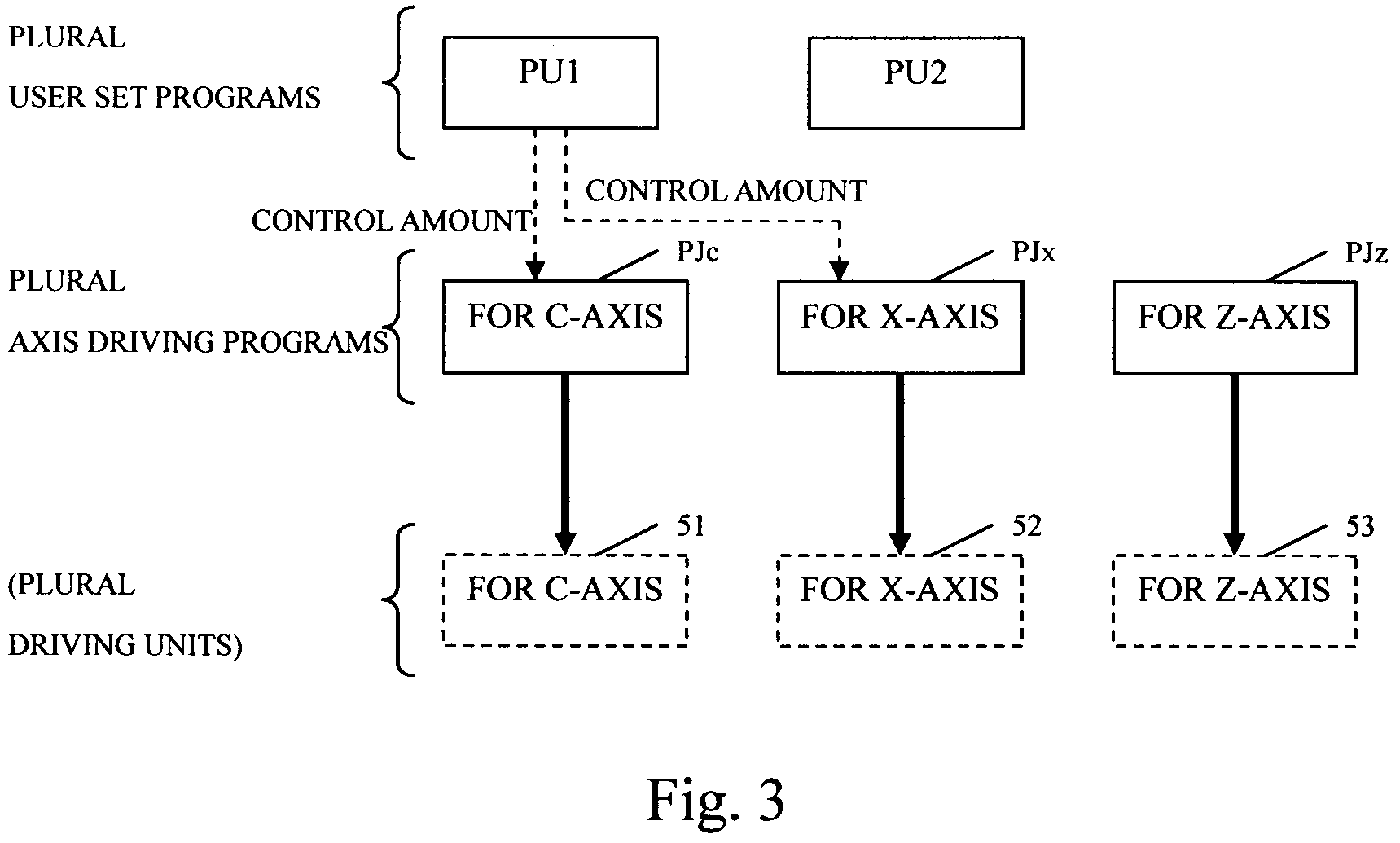
[0054]In the first embodiment of the present invention is explained the writing method of the plural user set programs that is not realized by the conventional writing method and an identification of each of independent motions in controlling at least one axis in the numerical controller. The user set program will be explained hereinafter.

[Cutting Machine 1 and Numerical Controller 40]

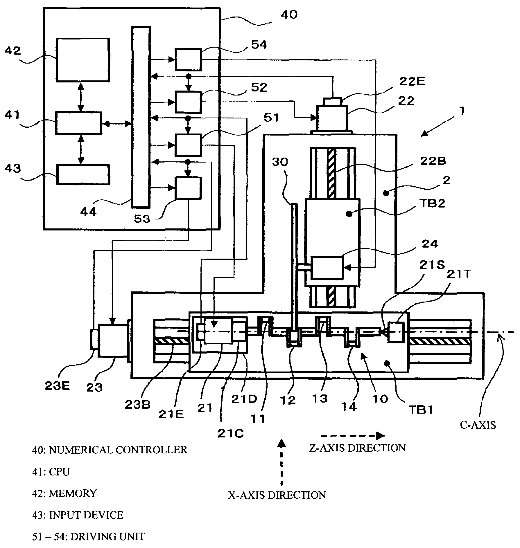
[0055]The cutting machine provides a base 2, a workpiece table TB1, a wheel table TB2 and the numerical controller 40.

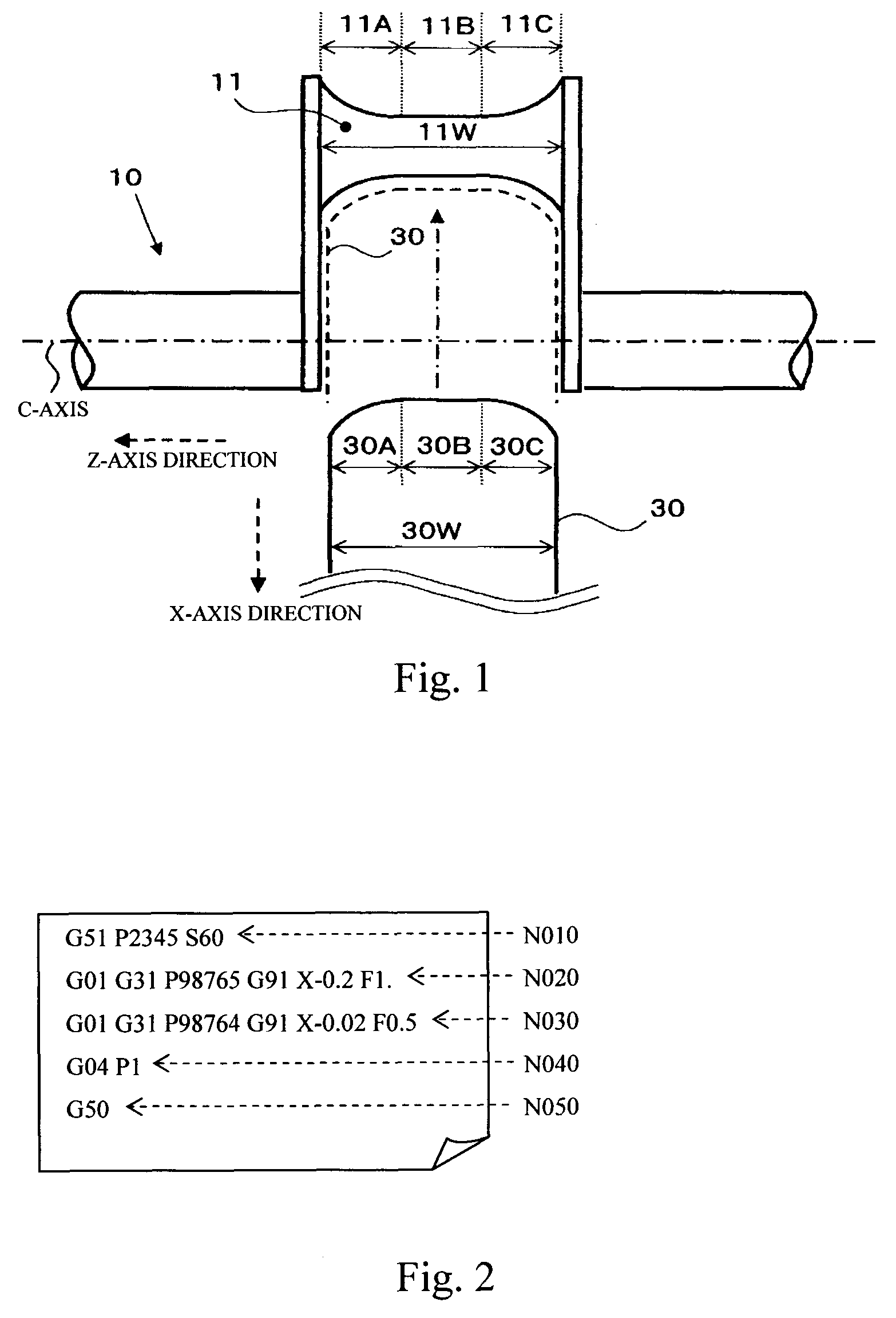
[0056]The wheel table TB2 has an approximately cylindrical grinding wheel 30 correspondent to the cutting tool. The grinding wheel 30 is rotated around a rotational axis parallel to the Z axis by a wheel rotational driving motor 24 mounted on the wheel table TB2. A width 30W of the grinding wheel 30 parallel to the rotational axis is smaller than a length 11W of the crankpin 11 along to the Z-axis as shown in FIG. 7. Besides, the Z-axis is parallel to the C-axis ...

second embodiment

of the Present Invention

[0094]The former publication of Tokkaisho 63-84845 discloses the step cutting method for the non-circular workpiece for grinding the cam to infeed the cutting tool by the amount of predetermined distances (ΔX) at short angular distances of one revolution of the cam shaft around the C-axis with the C-X profile motion. In this conventional cutting method, there is the possibility to occur the previously mentioned problem.

[0095]Therefore, in the second embodiment of the present invention, it will be explained the cutting machine having a continuous infeed at all peripheral position of the crankpin without concerning about the specific rotational angular position of the workpiece during the C-X profile motion of the C-axis and the X-axis by writing and performing individually different user set programs of the C-X profile motion of the C, X axes and the infeed motion along the X-axis in grinding the crankpin.

[0096]In the explanation of the second embodiment, ther...


PUM


Abstract

It is one object of the present invention to provide a program writing method of numerical controller, a numerical controller and a cutting machine controlled thereby, achieving the writing of a plurality of programs relating to one axis to perform a high efficiency in a lot of productions. A next or later user-set-program controlling a duplicated axis controlled by plural user set programs identifies a virtual axis virtually controlled by one user set program. A program is written to replace the duplicated axis with the virtual axis. A control amount calculated by the user set program identifying the virtual axis is added to a control amount inputted to a correspondent axis driving program as a control amount of the duplicated axis before replacing the virtual axis.

Description

INCORPORATION BY REFERENCE[0001]The present application claims priority under 35 U.S.C. §119 to Japanese Patent Applications No. 2006-265050, filed on Sep. 28, 2006 and No. 2006-265051, filed on Sep. 28, 2006. The content of these applications are incorporated herein by reference in their entirety.BACKGROUND OF THE INVENTION[0002]1. Field of the Invention[0003]The present invention relates to a program writing method of numerical controller, a numerical controller and a cutting machine controlled thereby, especially achieving to control plural axes by plural control programs.[0004]2. Description of the Related Art[0005]It is well known that there are several cutting machines and cutting methods for cutting portions of a workpiece rotatably supported by a headstock and a tailstock. Where a complete circle is formed on a peripheral profile of the cut portions of the rotated workpiece, it is performed relatively simple cutting to infeed gradually a cutting tool toward the workpiece in ...

Claims


Application Information

Patent Timeline
Patent Type & Authority Patents(United States)
IPC IPC(8): G06F19/00
CPCG05B19/184G05B19/4093G05B2219/36197G05B2219/45136G05B2219/49313G05B2219/50053Y02P90/02
Inventor YONEZU, TOSHIHIROSUGIURA, HIROAKIABETA, SATOSHI
Owner JTEKT CORP
Why Eureka
Try Eureka