
System and method for making photomasks

a photomask and photomask technology, applied in the field of photolithography, can solve the problems of limiting the wave properties of lithography, and making the achievement of the desired critical dimensions extremely difficult, and achieve the effect of the critical dimensions

Active Publication Date: 2010-10-19
TEXAS INSTR INC
View PDF15 Cites 2 Cited by
  • Summary
  • Abstract
  • Description
  • Claims
  • Application Information

AI Technical Summary

Benefits of technology

The patent text describes a method for determining the position of a photomask pattern in a mask making process. This is important for ensuring the proper placement of the patterns during the manufacturing of integrated circuit devices. The method involves using mask rules to determine the minimum spacing between photomask patterns and positioning the non-critical edge of a first photomask pattern relative to an adjacent second photomask pattern. This distance is chosen to be the minimum spacing allowed by the mask rules. The non-critical edge of the first photomask pattern is positioned a distance X from the edge of the second photomask pattern, where X is substantially the minimum spacing allowed by the mask rules. This method can be used in a multi-pattern process for patterning integrated circuit devices, and a computer-readable storage medium with an executable software program is also provided for this purpose.

Problems solved by technology

In general, these wave properties are seen as being a limiting factor in lithography.
However, the ever increasing densities of integrated circuit devices can make achieving the desired critical dimensions extremely difficult.

Method used


Image

  • System and method for making photomasks
  • System and method for making photomasks
  • System and method for making photomasks

Examples


Embodiment Construction

[0023]Reference is now made in detail to various embodiments of the present application, examples of which are illustrated in the accompanying drawings. The same reference numbers are used throughout the drawings to refer to the same or like parts.

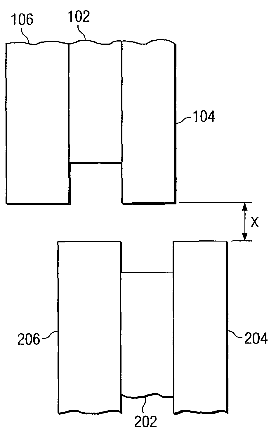
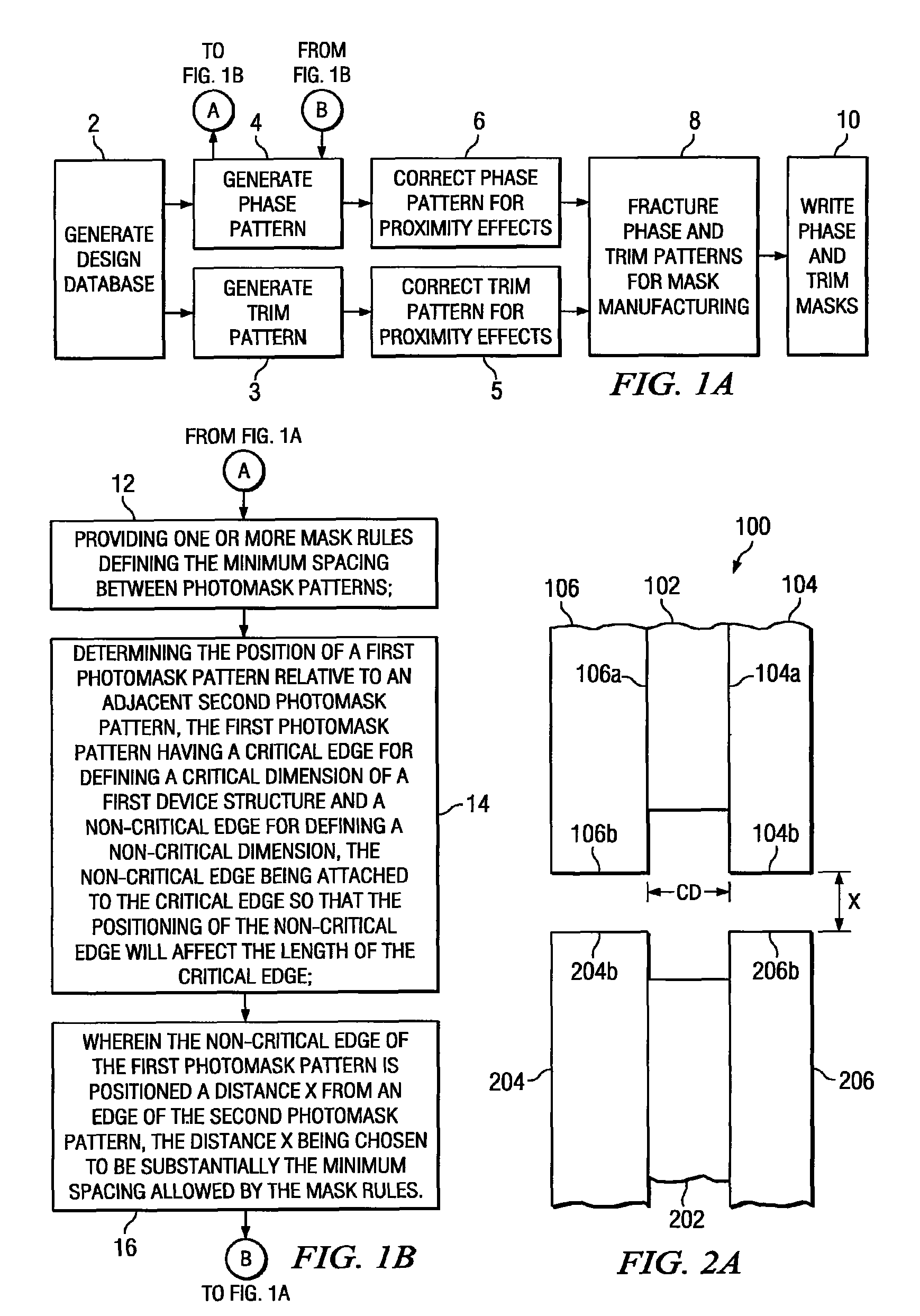
[0024]Photomask patterns that are used to generate photomasks generally include a plurality of polygon shaped patterns. The edges of these polygon patterns define boundaries that will be used to pattern a desired integrated circuit design to be fabricated. Every edge of the pattern can be assigned a different level of importance. Some pattern edges will be used to define critical dimensions of the integrated circuit design, such as, for example, a gate length. Other pattern edges may be used to pattern non-critical dimensions, such as interconnect widths or lengths, dummy features that are not a functional part of the device, ghost and trim features that may be subsequently removed, or gate ends formed over field regions.

[0025]In embodimen...


PUM

PropertyMeasurementUnit
distanceaaaaaaaaaa
distanceaaaaaaaaaa
distanceaaaaaaaaaa

Abstract

The present application is directed a method for determining the position of photomask patterns in a mask making process. The method comprises providing one or more mask rules defining the minimum spacing between photomask patterns. The method further comprises determining the position of a first photomask pattern relative to an adjacent second photomask pattern, the first photomask pattern having a critical edge for defining a critical dimension of a first device structure and a non-critical edge for defining a non-critical dimension. The non-critical edge is attached to the critical edge so that the positioning of the non-critical edge will affect the length of the critical edge. The non-critical edge of the first photomask pattern is positioned a distance X from an edge of the second photomask pattern, wherein the distance X is chosen to be substantially the minimum spacing allowed by the mask rules. Embodiments directed to software modules for implementing the method and patterning processes employing the method are also disclosed.

Description

[0001]This application is a Continuation-in-Part and claims the benefit of U.S. patent application Ser. No. 11 / 771,515, filed Jun. 29, 2007.FIELD OF THE DISCLOSURE[0002]The present application relates generally to the field of photolithography, and more specifically to a method and system for preparing a pattern for a photomask.BACKGROUND[0003]Conventional optical projection lithography has been the standard silicon patterning technology for the past 20 years. It is an economical process due to its inherently high throughput, thereby providing a desirable low cost per part or die produced. A considerable infrastructure (including steppers, photomasks, resists, metrology, etc.) has been built up around this technology.[0004]In this process, a photomask, or “reticle”, includes a semiconductor circuit layout pattern typically formed of opaque chrome, on a transparent glass (typically SiO2) substrate. A stepper includes a light source and optics that project light coming through the pho...

Claims


Application Information

Patent Timeline
Patent Type & Authority Patents(United States)
IPC IPC(8): G06F17/50G03F1/00
CPCG03F1/144G03F1/30G03F1/36G03F1/70
Inventor ATON, THOMAS J.
Owner TEXAS INSTR INC
Learn More