Handle apparatus

a technology for handle devices and handles, applied in the field of handle devices, can solve the problems of reducing the degree of freedom in design of the whole handle apparatus, and the inability to achieve the desired object, and achieve the effect of decreasing the degree of freedom in design

Active Publication Date: 2010-10-26
ALPHA +1
View PDF7 Cites 17 Cited by
  • Summary
  • Abstract
  • Description
  • Claims
  • Application Information

AI Technical Summary

Benefits of technology

[0009]One or more embodiments of the invention provide a handle apparatus adapted to surely prevent an illegal operation through an arm operation hole without decreasing a degree of freedom in design.
[0019]Accordingly, in the embodiments of the invention, since the blocking piece 8 and the rising piece 11 prevent a tool from being inserted into the inside of the door 2 through the arm insertion hole 6, it is not necessary to approach the blocking piece 8 to the opening end of the arm insertion hole 6 in the operational rotation position. For this reason, since it is not necessary to set an operational region of the blocking piece 8 to a surface close to the opening end of the arm insertion hole 6, a degree of freedom in arrangement of the blocking piece 8 increases, thereby easily performing a design thereof in consideration of interference with other components.
[0020]Further, since the operation surface of the blocking piece 8 is disposed away from the opening end of the arm insertion hole 6, it is possible to dispose a protrusion in a surface of the blocking piece 8 opposed to the arm insertion hole 6. As a result, for example, as shown in the drawing, since it is possible to use the blocking piece 8 as a connection portion of the transmission members with respect to the door lock apparatus 1, it is possible to efficiently use a space compared with the known example in which a surface of the blocking piece 8 opposed to the arm insertion hole 6 needs to be formed into a flat surface as a whole.
[0021]Furthermore, since the rising piece 11 erecting from the side edge of the blocking piece 8 serves as a regulation wall for preventing a case in which a tool moves along the blocking piece 8 while pressing against the front end of the blocking piece 8 so as to search the insertion path 10 to a position around the cylinder lock 9, it is possible to prevent an illegal operation.
[0022]Moreover, since when a blocking wall 12 erects from the handle base 3 so as to be positioned along the rising piece 11 of the swing lever 4 located in the operational rotation position, the blocking wall 12 serves as a wall for preventing a case in which a tool moves while sliding on the wall of the handle base 3 to the path 10 around the cylinder lock 9, it is possible to further prevent an illegal operation.
[0025]According to the embodiments of the invention, it is possible to surely prevent an illegal operation through an arm insertion hole without decreasing a degree of freedom in design.

Problems solved by technology

However, in the above handle apparatus, when a gap formed between the blocking portion and an opening end of the arm insertion hole is wide, a tool or the like may be inserted into a path formed in a slant direction so that a problem may arise in that a desired object may not be achieved.
However, since the swing lever as a movable member may interferes with other components like the handle base when they move, an another problem would arise in that a degree of freedom in design of a whole handle apparatus decreases by adding structures to the flat plate-like blocking portion having a predetermined area.
Additionally, since the blocking portion is formed into a flat plate shape, a problem may arise in that the front end of the tool or the like is inserted along the blocking portion and the blocking portion is used as a guide when searching the insertion hole.

Method used


Image

  • Handle apparatus
  • Handle apparatus
  • Handle apparatus

Examples


Embodiment Construction

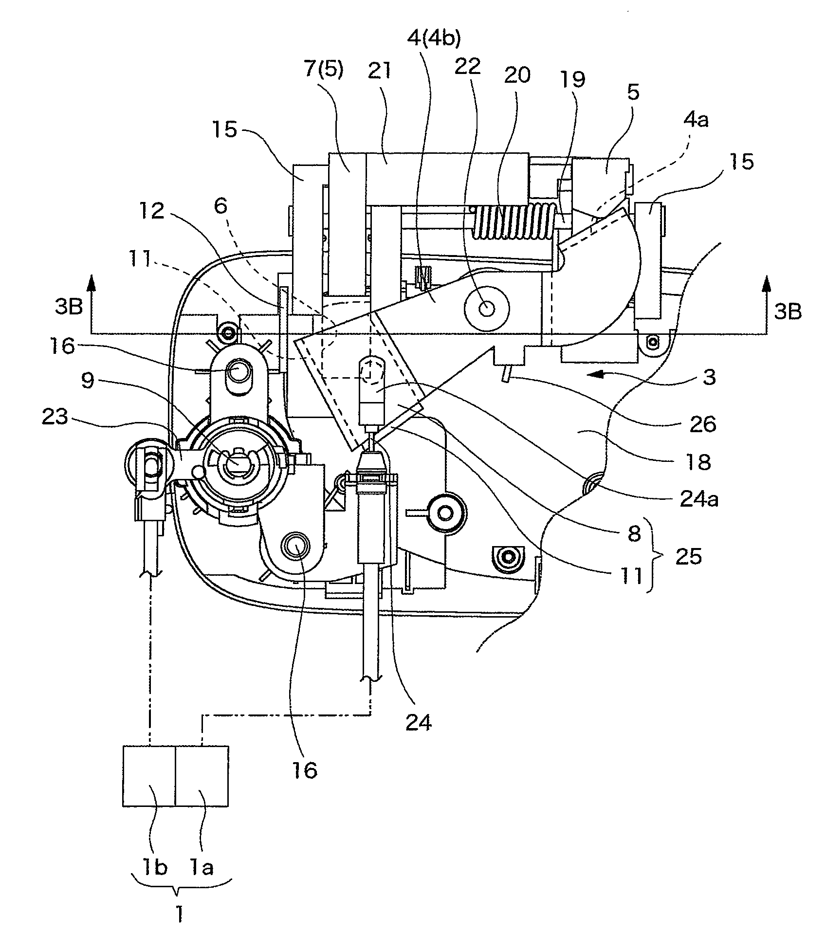
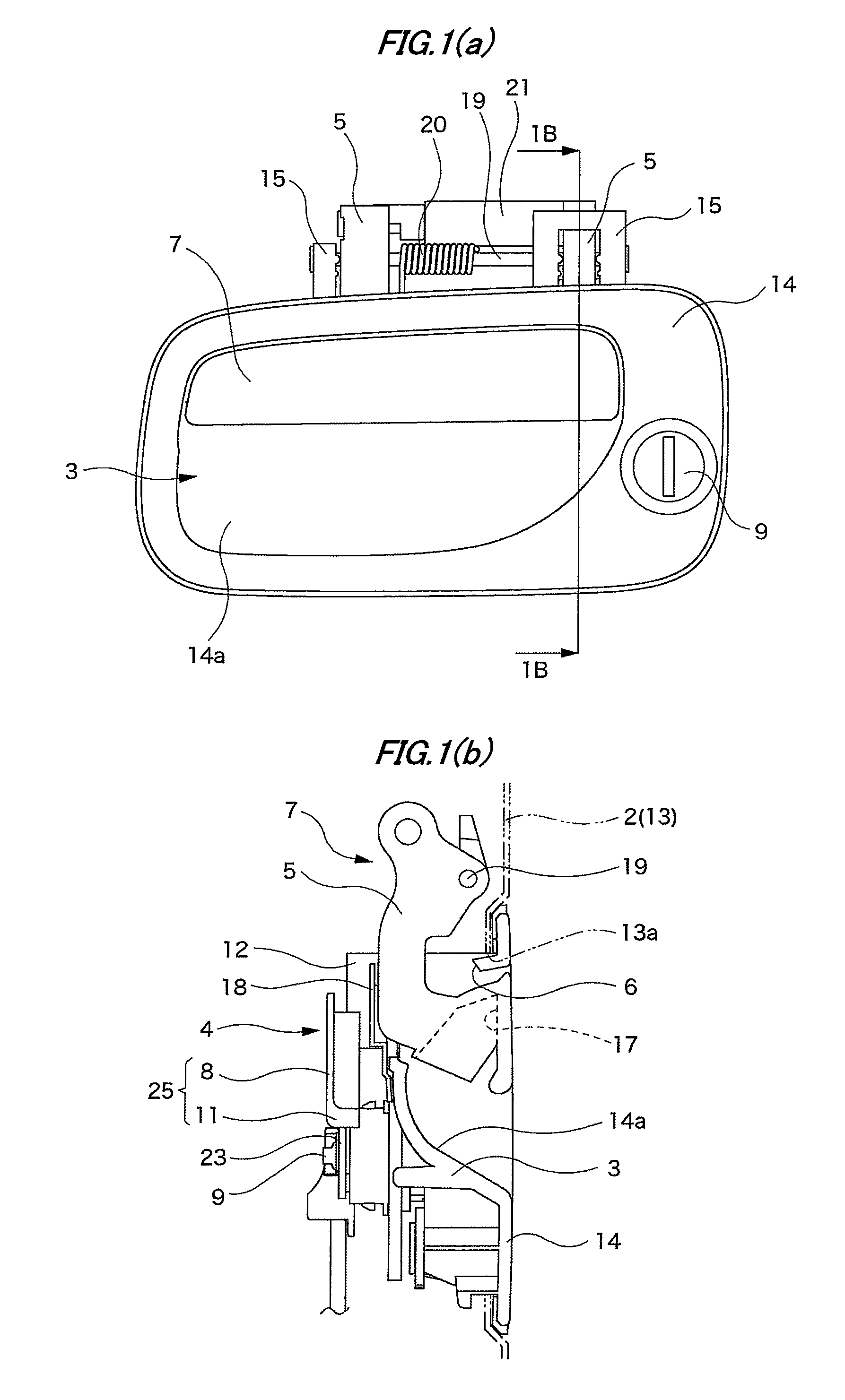
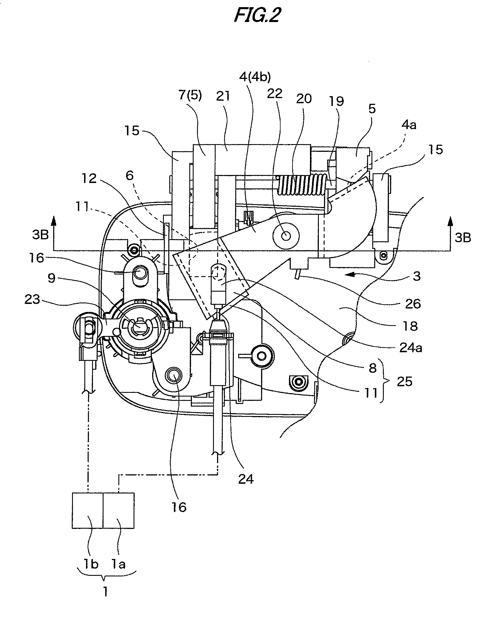
[0032]An exemplary embodiment of the invention will be described below in detail with reference to the accompanying drawings. As shown in FIGS. 1(a) and 1(b), a handle apparatus is configured such that a handle main body 7 is connected to a handle base 3, and the handle base 3 is fixed to a vehicle door 2 as shown in the drawing. A handle attachment hole 13a is formed through an outer panel 13 of the vehicle door 2 so that the handle apparatus is fixed thereto by inserting the handle apparatus therethrough from the outside of the vehicle door 2. Also, an escutcheon portion 14 is formed in the handle base 3 so as to block the handle attachment hole 13a. An end cover 18 is mounted between the escutcheon portion 14 and the outer panel 13.

[0033]The handle main body 7 includes two operation arms 5 which are formed in the rear surface of a handle portion 17 in a protruding manner. In order to expose only the handle portion 17 from the outer surface of the vehicle door 2, each of the opera...


PUM


Abstract

A handle apparatus is provided with: a handle base fixed to a door of a vehicle; a swing lever held inside the door and connected to the handle base to be vertically rotatable; a handle main body including an operation arm inserted inside the door through an arm insertion hole to drive the swing lever; a blocking piece on the swing lever for blocking the arm insertion hole from an inside of the door; and a rising piece protruding from a side edge of the blocking piece toward an outside of the door.

Description

[0001]This application claims foreign priority from Japanese Patent Application No. 2007-135649 filed on May 22, 2007, the entire contents of which are hereby incorporated by reference.BACKGROUND OF THE INVENTION[0002]1. Field of the Invention[0003]The present invention relates to a handle apparatus.[0004]2. Related Art[0005]JP-Y-06-023658 discloses a handle apparatus in which a door lock apparatus is operated by an operation to a handle main body. The handle apparatus is configured such that the handle main body is connected to a bracket (handle base). The handle main body includes an arm which is inserted into a rear surface of the handle base through an opening (arm insertion hole) formed through the handle base. Also, the handle base includes a swing lever which is driven to rotate by a rotation of the arm in accordance with a rotation of the handle main body.[0006]A flat plate-like blocking portion extends from the front end of the rotating swing lever. When the swing lever mov...

Claims


Application Information

Patent Timeline
Patent Type & Authority Patents(United States)
IPC IPC(8): E05B3/00B60J5/04E05B1/00E05B77/44E05B83/36E05B85/18
CPCE05B85/18Y10S292/31Y10S292/65Y10T292/57B60J5/04E05B85/10
Inventor KAGAWA, TAKAHIROABE, KEITA
Owner ALPHA
Why Eureka
Try Eureka