
Method and apparatus for harvesting and implanting bone plugs

a bone plug and bone plug technology, applied in medical science, surgery, vaccination/ovulation diagnostics, etc., can solve the problems of affecting the integrity of transplantation, so as to improve the integrity of the transplantation

Inactive Publication Date: 2010-10-26
INNOVASIVE DEVICES
View PDF67 Cites 15 Cited by
  • Summary
  • Abstract
  • Description
  • Claims
  • Application Information

AI Technical Summary

Benefits of technology

[0016]The present invention addresses the foregoing needs by providing, in one aspect, a bone plug implantation apparatus having a translucent and, preferably, a transparent or clear tip, through which the bone plug can be viewed during implantation. Unlike the prior art, inclusion of such a tip permits the surgeon to view the bone plug during implantation, thereby facilitating better placement, alignment and insertion of the plug into the donor site.
[0017]According to further aspects of the invention, the apparatus includes a “harvesting” tube which can be used to harvest the plug and which is used to hold the bone plug prior to implanting. The apparatus can also include a push rod that forces the bone plug into a pre-formed hole at the transplant site. The harvesting tube can include an aperture or recessed inner wall that reduces friction on the plug during implantation (and harvesting) and that, thereby, reduces undesirable compression of the plug.
[0018]According to further aspects of the invention, the tip has an inner diameter substantially equal to that of the hole into which the bone plug is transplanted. An outer diameter of the tip, however, can be greater than that of the hole. This larger outer diameter forms a shoulder upon which the tip can rest during implantation. The tip also covers the distal end of the harvesting tube and, hence, minimizes the damage that it might otherwise cause at the transplant site.
[0019]In still further aspects of the invention, the tip is rotatable relative to the harvesting tube. This facilitates rotation of the bone plug relative to the transplant site, e.g. so that their respective surfaces can be aligned and otherwise better fitted
[0020]According to still another aspect, the present invention provides an apparatus for harvesting plugs from bone tissue. The apparatus includes a harvesting tube, as described above, to which a cutting sheath is fitted. The sheath, which includes a cutting edge and a cutting tooth, can include markings on its outer surface so that the depth of insertion—and, therefore, the length of the bone plug—can be determined during harvesting. The harvesting tube can likewise include markings on its outer surface, e.g., adjacent the aforementioned window, so that the position and length of the plus can be more accurately determined after harvesting.
[0022]Still further aspects of the invention provide a drill guide for use in bone plug removal and replacement. The guide comprises a tip and a harvesting tube as described above. A drill bit is guided through the assembled tube / tip and is used to form a hole at the recipient site. Use of such an assembly as a drill guide can improve the integrity of the transplant, e.g., if the same (or similar) tube and tip are subsequently used during implantation of the plug.

Problems solved by technology

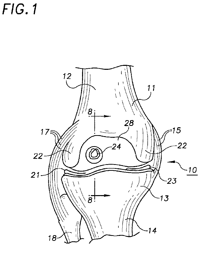
Weight-bearing joints, such as the knee, are particularly susceptible to injuries caused by friction between opposing bone surfaces.
Problems arise, however, if articular cartilage 28 becomes injured due to excessive near.
As a result of such injuries, osteochondritis and / or arthritis can develop, making movement of the joint painful In extreme cases, these conditions can result in disability if not treated.
The conventional instruments for harvesting bone plugs described above suffer from several drawbacks.
For example, it is difficult to regulate the size (i.e., the length) of bone plugs extracted by them.
Moreover, the bone plug tissue is sometimes unduly damaged or traumatized by excessive forces exerted during extraction or implantation.
Conventional instruments for implanting bone plugs also suffer from drawbacks.
Generally, it is difficult to gauge the exact depth of plug insertion and, thus, to avoid slight protrusions or cavities.
This problem is compounded in those instances where the donor and recipient sites do not have matching surface contours.

Method used


Image

  • Method and apparatus for harvesting and implanting bone plugs
  • Method and apparatus for harvesting and implanting bone plugs
  • Method and apparatus for harvesting and implanting bone plugs

Examples


Embodiment Construction

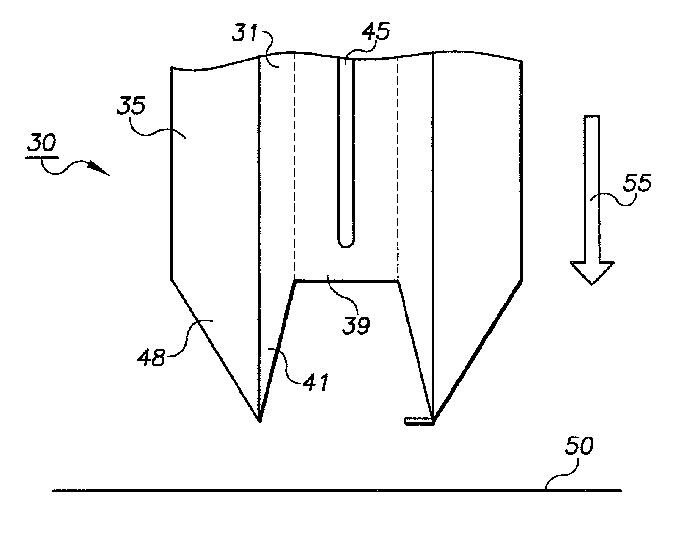
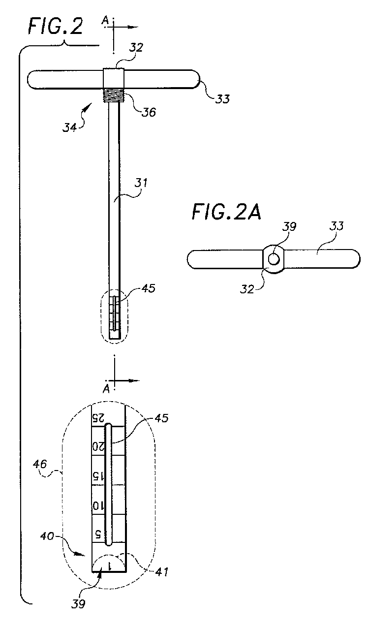
[0036]FIGS. 2 and 2B are front views of a device 30 according to the invention for harvesting a plug of bone tissue (i.e., bone and / or articular cartilage) from a donor site. Illustrated device 30 is generally configured in the manner of the harvesting apparatus described in U.S. Pat. No. 6,017,348 the teachings of which are incorporated herein by reference. The harvesting device 30 incorporates improvements on the apparatus of that prior application, as described below and elsewhere herein.

[0037]The device 30 includes harvesting tube 31, connector 32, handle 33, and cutting sheath 35. As shown in FIG. 2, handle 33 is attached to proximal end 34 of tube 31 and is used to facilitate driving the distal end of the device into the donor site and rotating the device to remove the plug. Illustrated handle 33 can be rod-like in construction, as illustrated, or it can be of other configurations, such as a knurled knob, hexagonal nut, or the like.

[0038]A connector 32 disposed at the junction...


PUM


Abstract

A system for transplanting a bone plug from a donor site to a recipient site extracts the bone plug from the donor site, and then places a bone plug delivery device having a tip which is at least translucent and, preferably, clear over a tube containing the bone plug. The tip is then placed substantially over a pre-formed hole in the recipient site, whereafter the bone plug is forced from the tube, through the transparent tip, and into the pre-formed hole.

Description

CROSS-REFERENCE TO RELATED APPLICATIONS[0001]The present application is a continuation of U.S. patent application Ser. No. 10 / 004,388 (now U.S. Pat. No. 6,767,354) filed on Oct. 23, 2001, which is a divisional application of U.S. patent application Ser. No. 09 / 118,680 (now U.S. Pat. No. 6,359,011) filed on Jul. 17, 1998, which are hereby incorporated by reference in their entiretiesBACKGROUND OF THE INVENTION[0002]The present invention is directed to methods and apparatus for harvesting and implanting bone plugs. The invention has particular utility in repairing damaged bone tissue, such as articular cartilage and underlying subchondral cancellous bone in the knee and other weight-bearing joints.[0003]Weight-bearing joints, such as the knee, are particularly susceptible to injuries caused by friction between opposing bone surfaces. To understand the causes of such injuries, it is first necessary to understand the anatomy of a such a joint. In this regard, FIG. 1 illustrates knee joi...

Claims


Application Information

Patent Timeline
IPC IPC(8): A61B17/14A61B10/00A61B10/02A61B17/00A61B17/16A61B17/32A61B17/34
CPCA61B10/025A61B17/1635A61B17/32053A61B17/3468A61B17/3472A61B17/1637A61B2017/00969
Inventor JOHANSON, MARK A.BARNES, BILLROSE, DONALD J.
Owner INNOVASIVE DEVICES
Learn More