
Locally adapted hierarchical basis preconditioning

a hierarchical basis and preconditioning technology, applied in the field of data processing in finite element analysis, can solve the problems of affecting the efficiency of direct methods for solving sparse systems, the performance of iterative algorithms usually degrades, and the best technique for smooth varying (homogeneous) problems, so as to improve the condition number of a matrix, simplify computations involving such matrices, and reduce computational overhead

Inactive Publication Date: 2010-10-26
MICROSOFT TECH LICENSING LLC
View PDF11 Cites 11 Cited by
  • Summary
  • Abstract
  • Description
  • Claims
  • Application Information

AI Technical Summary

Benefits of technology

This approach significantly reduces computational overhead and improves the quality of image outputs by optimizing the preconditioning process for highly inhomogeneous 2D interpolation / reconstruction problems, enhancing the performance of iterative solutions.

Problems solved by technology

Such problems also include various physically-based modeling problems such as elastic surface dynamics and the regularized solution of computer vision problems such as surface reconstruction, optic flow, and shape from shading.
Direct methods for solving sparse systems become inefficient for large multi-dimensional problems because of excessive amounts of fill-in that occurs during the solution.
Unfortunately, as the problems become larger, the performance of iterative algorithms usually degrades due to the increased condition number of the associated systems.
Unfortunately, such techniques work best for smoothly varying (homogeneous) problems, which is often not the case for many finite element or computer graphics applications.
Unfortunately, while multi-level preconditioners have proven to be quite effective at accelerating the solution of such tasks, some problems remain.
In addition, such algorithms perform poorly on problems with large amounts of inhomogeneity, such as local discontinuities or irregularly spaced data.

Method used


Image

  • Locally adapted hierarchical basis preconditioning
  • Locally adapted hierarchical basis preconditioning
  • Locally adapted hierarchical basis preconditioning

Examples


Embodiment Construction

[0034]In the following description of various embodiments of the present invention, reference is made to the accompanying drawings, which form a part hereof, and in which is shown by way of illustration specific embodiments in which the invention may be practiced. It is understood that other embodiments may be utilized and structural changes may be made without departing from the scope of the present invention.

[0035]1.0 Exemplary Operating Environment:

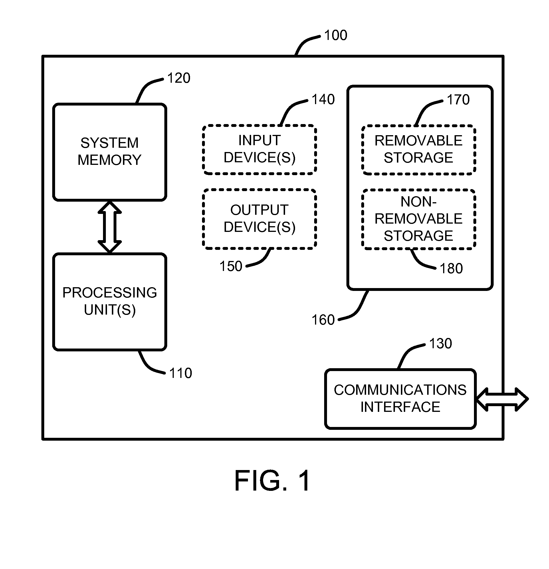
[0036]FIG. 1 illustrates an example of a simplified computing environment on which various embodiments and elements of a “Finite Element Preconditioner,” as described herein, may be implemented. It should be noted that any boxes that are represented by broken or dashed lines in FIG. 1 represent alternate embodiments of the simplified computing environment, as described herein, and that any or all of these alternate embodiments, as described below, may be used in combination with other alternate embodiments that are described throughout...


PUM


Abstract

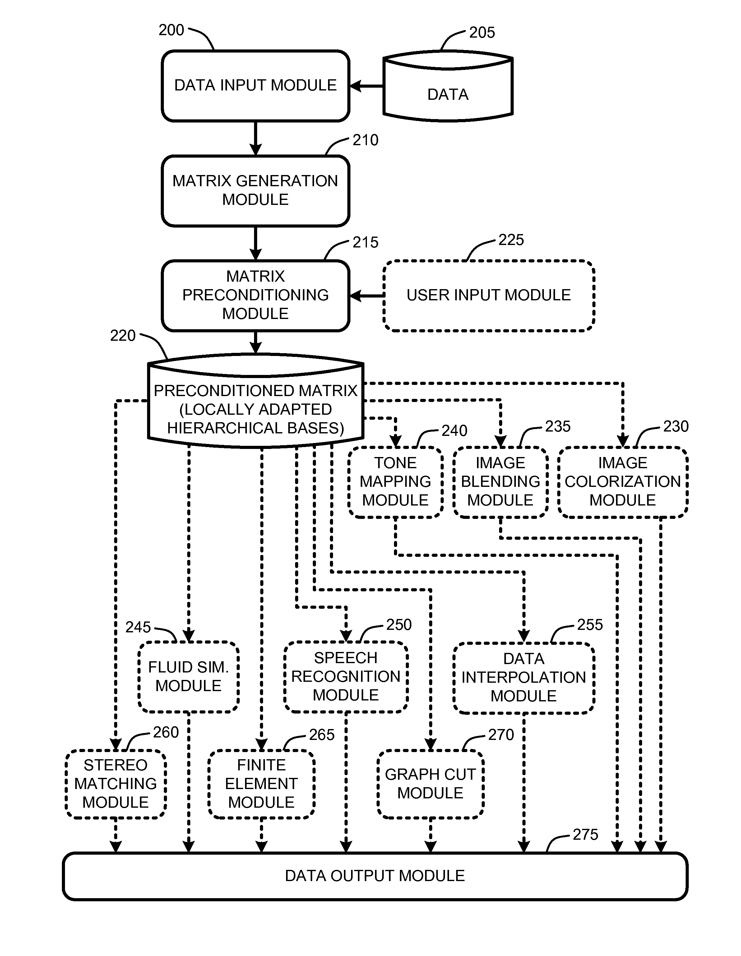
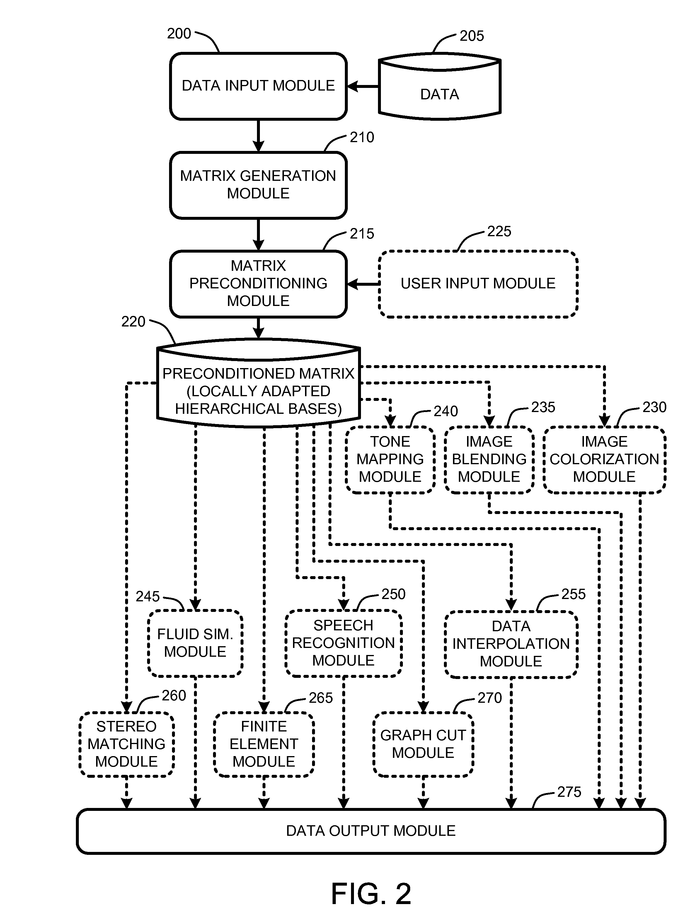
A “Finite Element Preconditioner” provides locally adapted hierarchical basis functions for preconditioning large data optimization problems. For example, a few of the many typical graphics applications that make use of iterative optimization solutions include tone mapping, gradient domain blending, colorization, and scattered data interpolation. Preconditioning image data for such optimization problems allows those image optimization problems to be solved using less computational overhead and therefore to produce better quality image outputs with less computational overhead. The Finite Element Preconditioner evaluates data, such as image data, to adapt hierarchical basis functions to inhomogeneous problems for preconditioning large optimization problems. Specifically, the Finite Element Preconditioner evaluates the local structure of a coefficient matrix derived from the data and performs a recursive set of variable eliminations, combined with a simplification of the resulting coarse level problems to obtain bases better suited for problems with inhomogeneous (spatially varying) data, smoothness, and boundary constraints.

Description

BACKGROUND[0001]1. Technical Field[0002]The invention is related to data processing in finite element analysis, and in particular, to a technique for adapting hierarchical basis functions to inhomogeneous problems for preconditioning large optimization problems.[0003]2. Related Art[0004]Many finite element analysis problems, including many computer graphics problems, can be formulated as the solution of a set of spatially-varying linear or non-linear partial differential equations (PDEs). A few of the many such problems include computational photography algorithms such as high-dynamic range tone mapping, Poisson and gradient-domain blending, and colorization. Such problems also include various physically-based modeling problems such as elastic surface dynamics and the regularized solution of computer vision problems such as surface reconstruction, optic flow, and shape from shading. Techniques for addressing such continuous variational problems are well known to those skilled in the...

Claims


Application Information

Patent Timeline
Patent Type & Authority Patents(United States)
IPC IPC(8): G06K9/36G06K9/40
CPCG06F17/13
Inventor SZELISKI, RICHARD
Owner MICROSOFT TECH LICENSING LLC
Learn More