Firefighting device with light emitting component

a technology of light-emitting components and firefighting devices, which is applied in the direction of fixed installation, combustion types, lighting and heating apparatuses, etc., can solve the problems of inability to see firefighters in front of their faces, inability to temporarily separate firefighters from each other and their equipment, and difficulty in ensuring etc., to achieve the effect of increasing the visibility of firefighting devices, reducing visibility, and increasing the safety of firefighters

Active Publication Date: 2010-11-02
ELKHART BRASS MFG
View PDF28 Cites 29 Cited by
  • Summary
  • Abstract
  • Description
  • Claims
  • Application Information

AI Technical Summary

Benefits of technology

[0006]According to the present invention, a component is provided that increases the visibility of firefighting devices or equipment to which the component is mounted to thereby increase the safety of the fire fighters particularly during an interior fire attack and suppression where visibility is severely reduced if not non-existent.
[0011]In another form of the invention, a firefighting nozzle includes a nozzle body with a fluid passage through which a fluid flows when the nozzle is in operation. The nozzle body includes at least one molded body. For example, the body may be molded from a rubber, an elastomer or a polymer material, which is at least translucent. The firefighting nozzle also includes a light emitting source. Light emitted from the light emitting source is emitted from the molded body, which either covers or encapsulates the light emitting source, to illuminate the firefighting nozzle.
[0014]Accordingly, the present invention provides a firefighting component that can provide a tangible increase to firefighting safety to make the firefighting device or equipment to which the firefighting component is mounted more visible during a low light or no-light condition.

Problems solved by technology

It is expected that during interior operations, firefighters will struggle to see their hands in front of their faces.
However, reflective tape / labels require the presence of a light—one additional item that a fire fighter must carry into an unknown and dangerous area.
Because interior attack can be extremely dangerous, firefighters are taught never to separate from their hose line or their partners.
However, in an event such as a partial collapse of the structure, it is possible that fire fighters can become temporarily separated from each other and their equipment.

Method used


Image

  • Firefighting device with light emitting component
  • Firefighting device with light emitting component
  • Firefighting device with light emitting component

Examples


Embodiment Construction

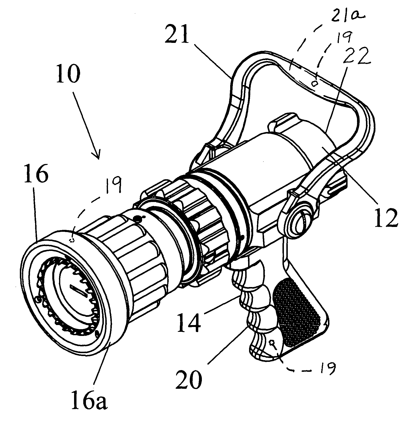
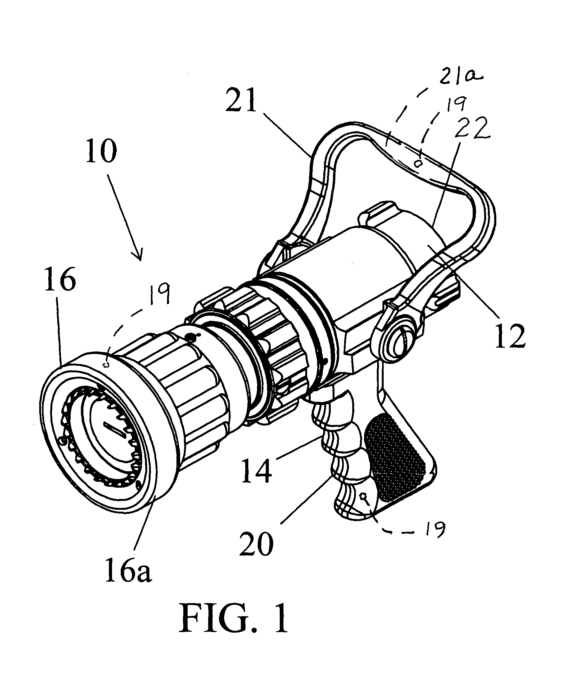
[0025]Referring to FIG. 1, the numeral 10 generally designates a nozzle. As will be more fully described below, nozzle 10 includes one or more molded components that are adapted to emit light from a light source to enhance the safety to firefighters in the region of the nozzle by providing them a greater ability to locate the nozzle and their equipment and potentially locate a path to exit the structure. While the present invention is described in reference to a nozzle, it should be understood that the invention may be incorporated in other firefighting devices such as monitors, hoses, gated wyes, or the like.

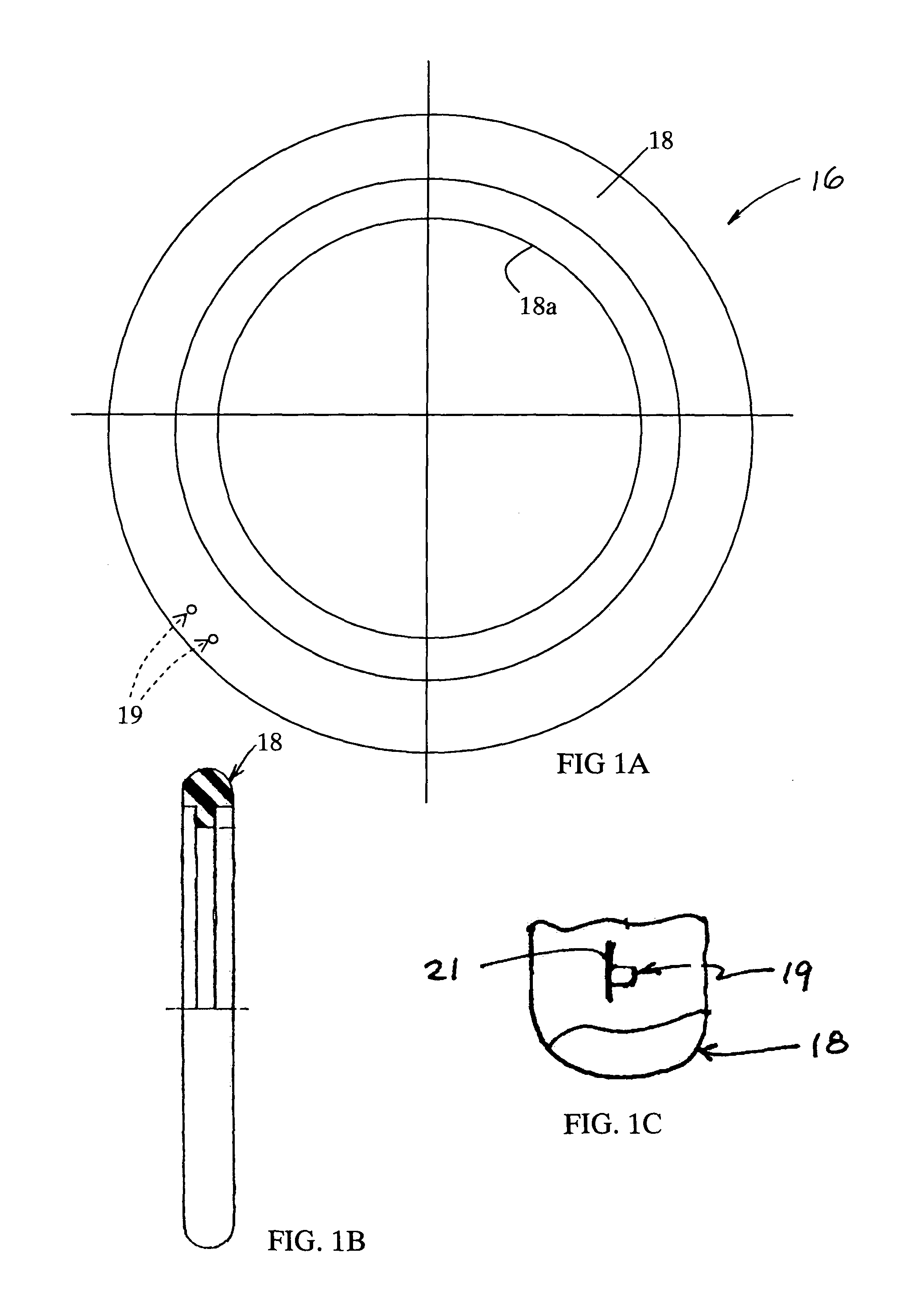
[0026]In the illustrated embodiment, nozzle 10 comprises a hand-line nozzle. Nozzle 10 includes a nozzle body 12 with a handle 14 and a bumper 16, which is mounted to the nozzle at the nozzle exit. Nozzle body 12 is typically formed from brass or aluminum and, therefore, subject to impact damage unless protected, for example, by bumper 16. Referring to FIGS. 1A and 1B, bumper 1...


PUM


Abstract

A firefighting device comprising includes a device body with a fluid passage through which a fluid flows when the firefighting device is in operation and at least one molded body. At least a portion of the molded body is at least translucent and encloses therein or covers a light emitting source. When light is emitted from the light emitting source, light is emitted from the molded body to thereby illuminate the firefighting device.

Description

CROSS-REFERENCE TO RELATED APPLICATIONS[0001]This application claims the benefit and priority to Provisional Application Ser. No. 60 / 724,823, filed Oct. 7, 2005, entitled FIREFIGHTING DEVICE WITH LIGHT EMITTING COMPONENT, and is incorporated by reference herein in its entirety.TECHNICAL FIELD AND BACKGROUND OF THE INVENTION[0002]The present invention relates to components for firefighting devices and, more particularly, to molded components or accessories that are attached to firefighting devices, such as nozzles, monitors, fire hoses, gated wyes, or the like.[0003]Firefighting nozzles, both handline and master stream device nozzles, generally have a molded rubber, elastomer or polymer bumper attached to the exterior of the nozzle exit. As nozzles tend to be made of either aluminum or brass, both comparatively soft materials and subject to impact damage, the bumper serves to protect the end of the nozzles from incidental damage. Nozzle bumpers are generally available in a variety of...

Claims


Application Information

Patent Timeline
Patent Type & Authority Patents(United States)
IPC IPC(8): F21S8/00
CPCA62C31/02B05B15/00F21V15/04F21V31/04F21V33/0064F21V9/16F21Y2101/02F21Y2105/00F21Y2115/10F21V9/30
Inventor MCGARRY, KIERNANLOZIER, TODD
Owner ELKHART BRASS MFG
Why Eureka
Try Eureka