Control system for supplying fluid medium to endoscope
a technology of fluid control system and endoscope, which is applied in the field of endoscopy, can solve the problems of inconvenient and laborious maintenance of the endoscope provided with the above mentioned fluid control system, and insufficiently preventing the entry of contaminated debris, so as to achieve convenient and simple operation and maintenance, and reliably prevent the entry of contamination
- Summary
- Abstract
- Description
- Claims
- Application Information
AI Technical Summary
Benefits of technology
Problems solved by technology
Method used
Image
Examples
first embodiment
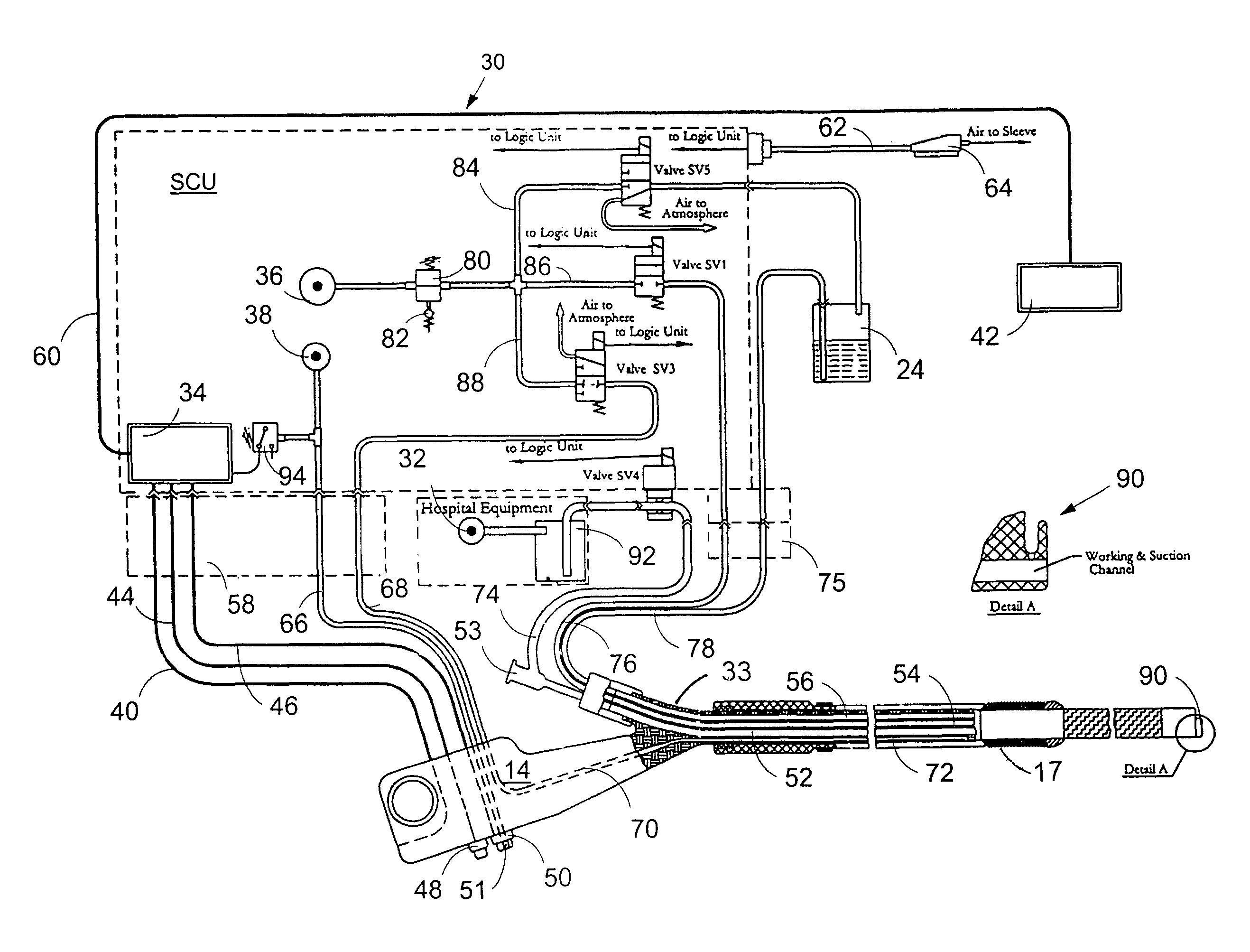
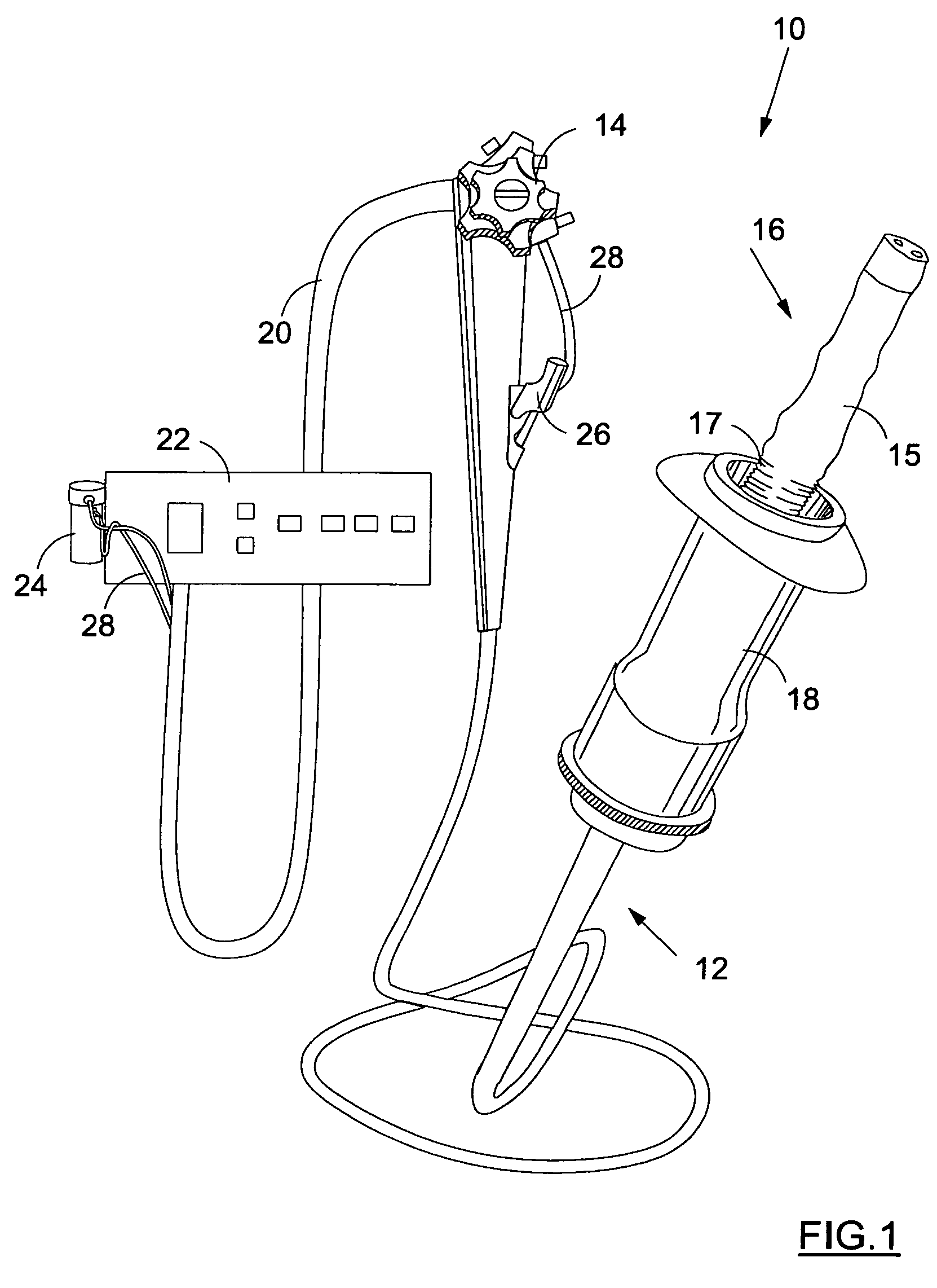
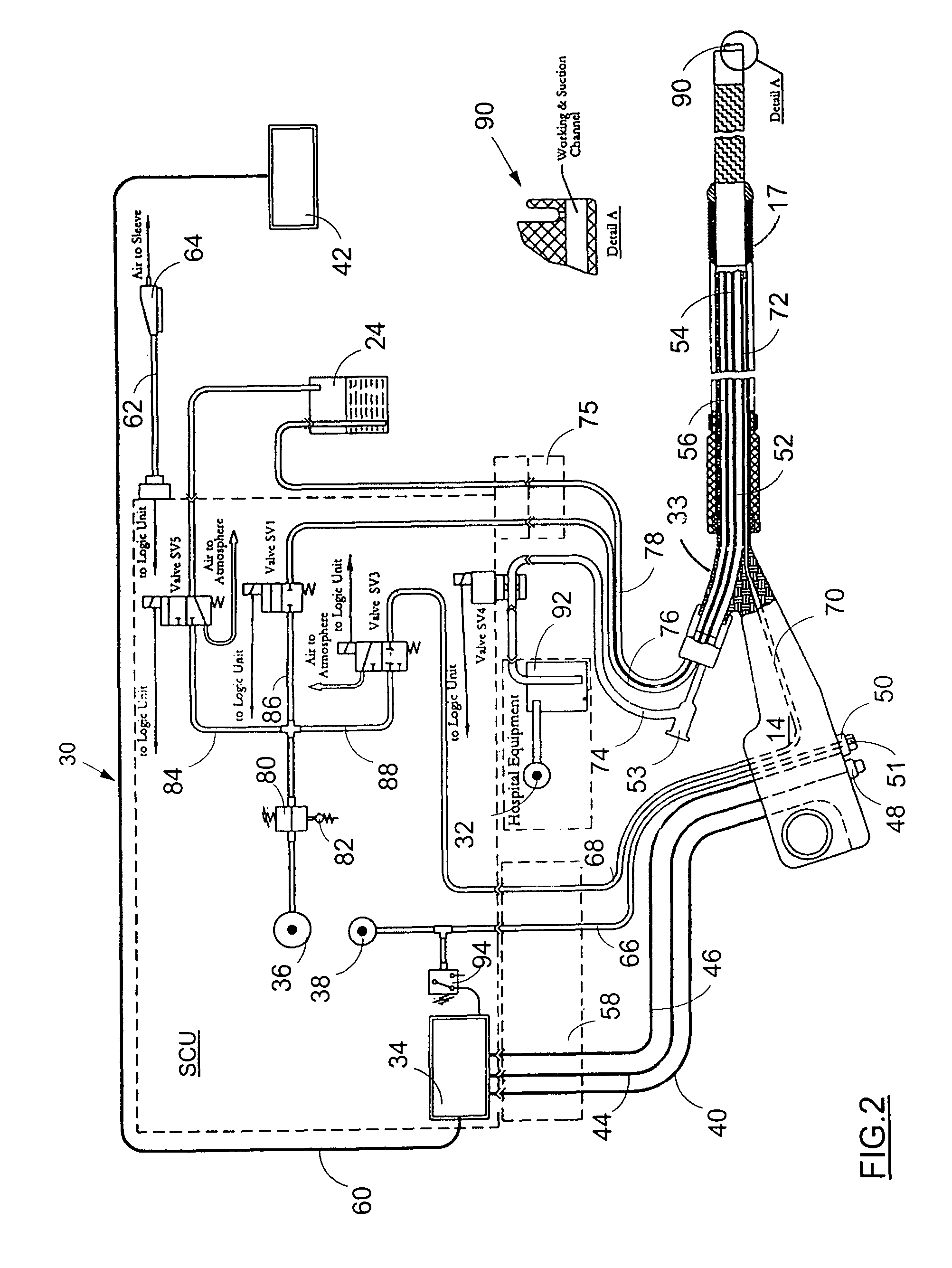
[0022]Referring now to FIG. 2 the fluid control system of the invention is seen. The system is designated by reference numeral 30 and its main component, i.e. the SCU is designated schematically by a dotted line. The SCU controls supply of air, water and vacuum as required for proper functioning of the colonoscopic apparatus 10. Some external components of the fluid control system, namely flask 24 and vacuum pump unit 32, are also seen. In practice the flask volume should be sufficient to contain about 300 cc of water. As a suitable source of vacuum one could use available hospital equipment capable of producing a vacuum of −0.4 bar to enable suction from the body passage through the multilumen tubing with a flow rate of at least 20 liter per minute. The multilumen tubing is seen in FIG. 2 and it is designated by reference numeral 33.
[0023]Within the SCU are provided the necessary electronic, pneumatic and hydraulic components, e.g. a logic unit 34, a first and a second pump 36,38 f...
second embodiment
[0042]Now the present invention will be explained. This embodiment is depicted in FIG. 3 and FIG. 4 and it is intended to reduce as much as possible the probability of contamination from the body passage through the sleeve when it becomes punctured. Referring to FIG. 3 it is seen that most of the components of the system remain the same, however in contrast to the previous embodiment in the supply line a) there is provided a contamination trap means 96, which is located between the handle and valve SV3. In practice it would be preferable if the trap means resides within the connector 58 as seen in FIG. 3.
[0043]The trap means is intended to prevent entrance of any contamination back to the SCU when flow communication is provided between the body channel or cavity and the SCU via channel 72, passage 70 and tube 68. Construction and functioning of the trap means will be explained in more details with reference to FIG. 4.
[0044]Referring again to FIG. 3 it is also seen that duct 88 split...
PUM
 Abstract
Description
Claims
Application Information
 - R&D
- Intellectual Property
- Life Sciences
- Materials
- Tech Scout
- Unparalleled Data Quality
- Higher Quality Content
- 60% Fewer Hallucinations
Browse by: Latest US Patents, China's latest patents, Technical Efficacy Thesaurus, Application Domain, Technology Topic, Popular Technical Reports.
© 2025 PatSnap. All rights reserved.Legal|Privacy policy|Modern Slavery Act Transparency Statement|Sitemap|About US| Contact US: help@patsnap.com


