Control system for supplying fluid medium to endoscope

a technology of fluid control system and endoscope, which is applied in the field of endoscopy, can solve the problems of inconvenient and laborious maintenance of the endoscope provided with the above mentioned fluid control system, and insufficiently preventing the entry of contaminated debris, so as to achieve convenient and simple operation and maintenance, and reliably prevent the entry of contamination

Inactive Publication Date: 2006-03-09
STRYKER GI
View PDF36 Cites 23 Cited by
  • Summary
  • Abstract
  • Description
  • Claims
  • Application Information

AI Technical Summary

Benefits of technology

[0009] A further object of the invention is to provide a new and improved system and system control unit, which is convenient and simple in operation and maintenance.
[0010] Still a further object

Problems solved by technology

Unfortunately maintenance of the endoscope provided with the above mentioned fluid control system is inconvenient and labor consuming, since before putting it into operation each tube should be connected one by one with a

Method used


Image

  • Control system for supplying fluid medium to endoscope
  • Control system for supplying fluid medium to endoscope
  • Control system for supplying fluid medium to endoscope

Examples


first embodiment

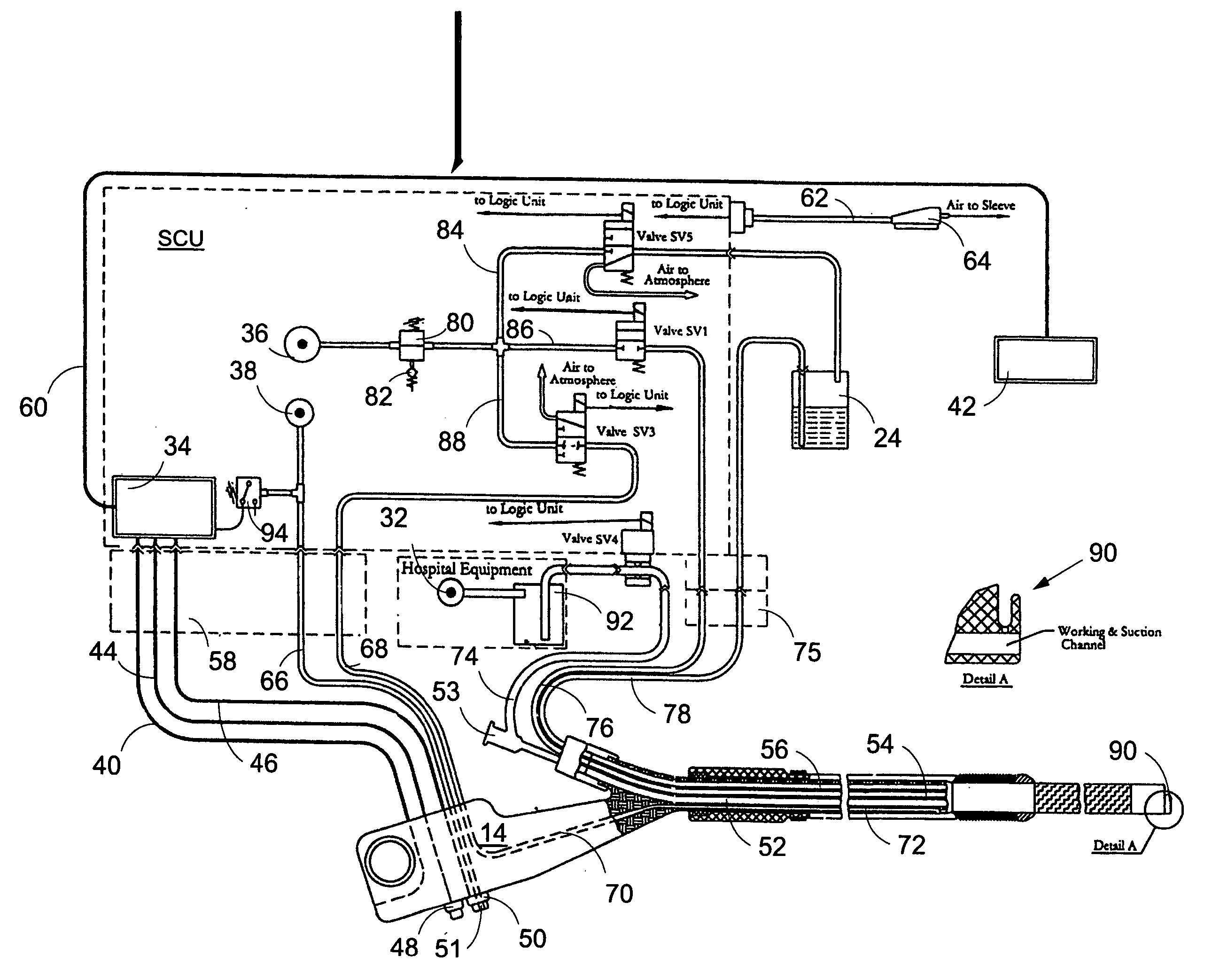
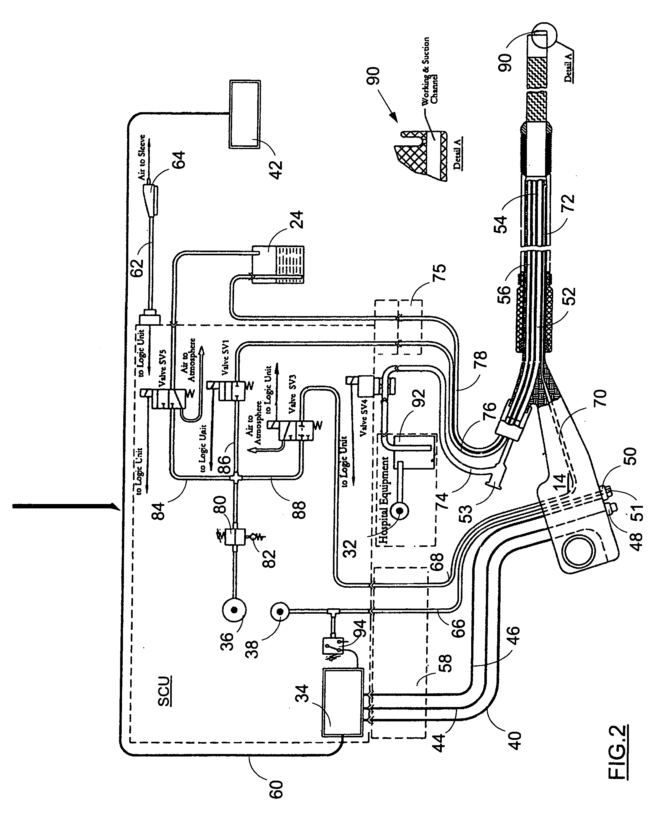
[0022] Referring now to FIG. 2 the fluid control system of the invention is seen. The system is designated by reference numeral 30 and its main component, i.e. the SCU is designated schematically by a dotted line. The SCU controls supply of air, water and vacuum as required for proper functioning of the colonoscopic apparatus 10. Some external components of the fluid control system, namely flask 24 and vacuum pump unit 32, are also seen. In practice the flask volume should be sufficient to contain about 300 cc of water. As a suitable source of vacuum one could use available hospital equipment capable of producing a vacuum of −0.4 bar to enable suction from the body passage through the multilumen tubing with a flow rate of at least 20 liter per minute. The multilumen tubing is seen in FIG. 2 and it is designated by reference numeral 33.

[0023] Within the SCU are provided the necessary electronic, pneumatic and hydraulic components, e.g. a logic unit 34, a first and a second pump 36,38...

second embodiment

[0042] Now the present invention will be explained. This embodiment is depicted in FIG. 3 and FIG. 4 and it is intended to reduce as much as possible the probability of contamination from the body passage through the sleeve when it becomes punctured. Referring to FIG. 3 it is seen that most of the components of the system remain the same, however in contrast to the previous embodiment in the supply line a) there is provided a contamination trap means 96, which is located between the handle and valve SV3. In practice it would be preferable if the trap means resides within the connector 58 as seen in FIG. 3.

[0043] The trap means is intended to prevent entrance of any contamination back to the SCU when flow communication is provided between the body channel or cavity and the SCU via channel 72, passage 70 and tube 68. Construction and functioning of the trap means will be explained in more details with reference to FIG. 4.

[0044] Referring again to FIG. 3 it is also seen that duct 88 s...


PUM


Abstract

A control system for supplying fluid medium to an endoscopic apparatus which comprises an operation handle and an insertion tube provided with an insufflation channel, an irrigation channel and a suction channel extending therealong. The control system is provided with a system control unit with at least one source of a first fluid medium, with a source of a second fluid medium, with a source of vacuum and with a multifunctional connector for bringing the operation handle in fluid and electrical communication with the system control unit. The source of the first fluid medium and the source of the second fluid medium are simultaneously connectable to and disconnectable from the insufflation channel and the irrigation channel.

Description

FIELD OF THE INVENTION [0001] The present invention relates generally to the field of endoscopy and specifically to endoscopic apparatus used for colonoscopic procedures during which a flexible tube is inserted into the rectum and colon for examination of the colon interior for abnormalities. More particularly, the present invention refers to a control system for supplying a fluid medium, e.g. air, water etc. to the endoscope. BACKGROUND OF THE INVENTION [0002] There are known endoscopes employing inflatable flexible sleeves for propulsion endoscope within colon. [0003] Voloshin (U.S. Pat. No. 6,485,409) discloses an endoscope, which comprises an endoscopic probe, a bending section for directing the probe within the colon (steering unit), an insertion tube and a flexible covering sleeve or a sheath, which is coupled proximally to the probe. The bending section of the endoscope is located behind the probe. The sleeve is attached to the endoscope in such a manner that its folded secti...

Claims


Application Information

Patent Timeline
IPC IPC(8): A61B1/12
CPCA61B1/00142A61B1/00154A61M13/003A61B1/018A61M1/0058A61B1/015A61M1/77A61B1/12A61M1/00
Inventor AIZENFELD, AMRAMLEVIN, VICTORSALMAN, GOLANSHEZIFI, OMEROZ, DANLEVY, AVI
Owner STRYKER GI
Why Eureka
Try Eureka