
System and method for variable depth ultrasound treatment

a variable depth and ultrasound technology, applied in the field of ultrasound systems, can solve the problems of difficult control of the focal spot location and the need for acoustic energy to pass through, and achieve the effects of high acoustic power, good imaging capabilities, and sufficient bandwidth

Active Publication Date: 2010-11-02
GUIDED THERAPY SYSTEMS LLC
View PDF201 Cites 181 Cited by
  • Summary
  • Abstract
  • Description
  • Claims
  • Application Information

AI Technical Summary

Benefits of technology

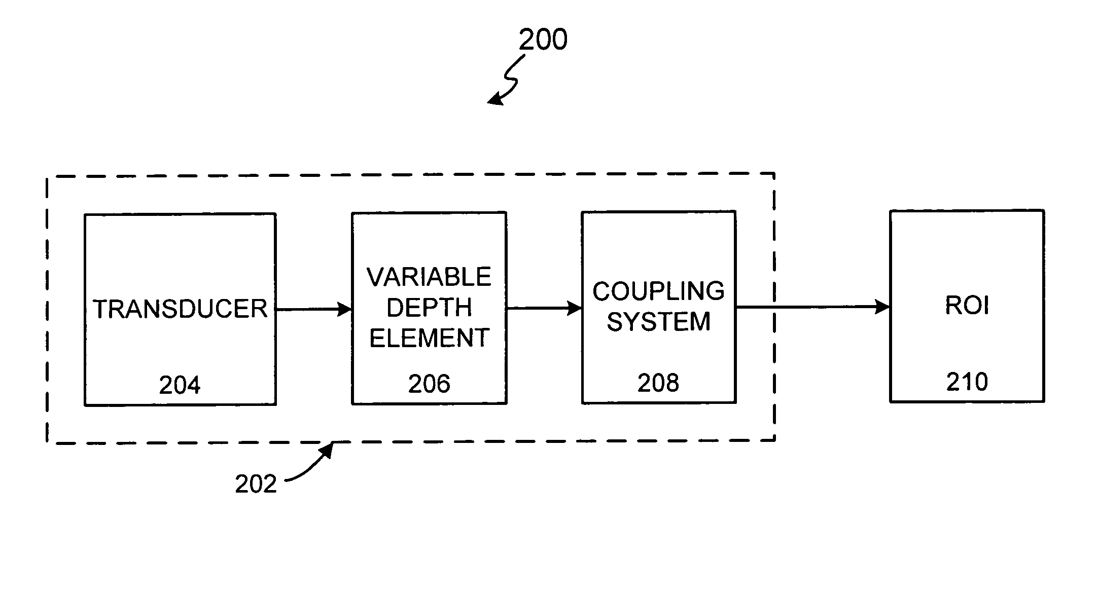
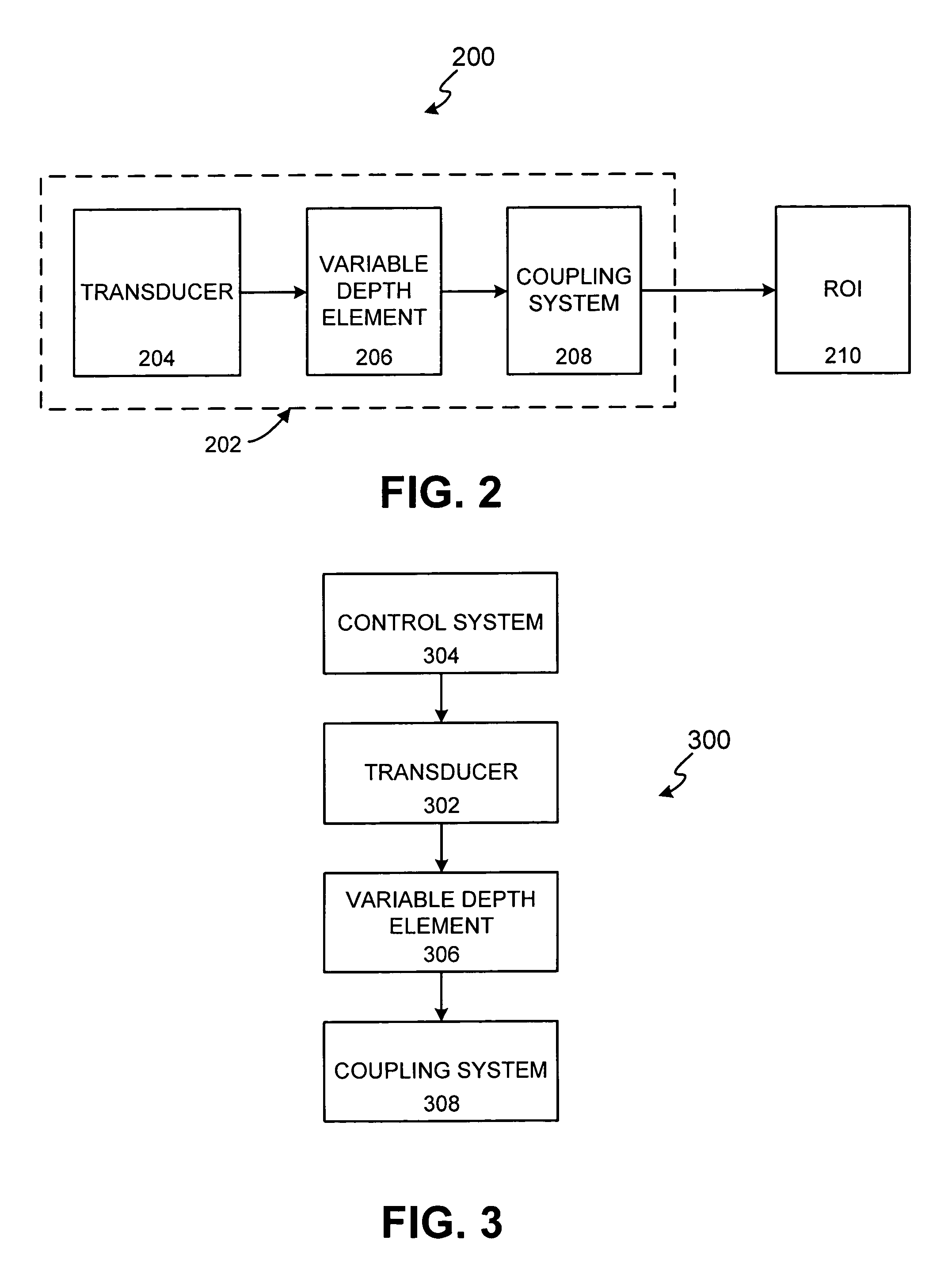
The present invention provides a variable depth ultrasound treatment method and system that can provide treatment to multiple regions of interest in a body. The system can change the location, shape, and size of the treatment region, as well as the thermal conditions, by controlling the distance between the treatment transducer and the reflecting surface, and by controlling changes in frequency, drive amplitude, and timing of the transducer. The treatment can be provided using a single transducer or an array of sub-elements. The system can also provide therapeutic heating, cooling, and imaging of the treatment region, and can adjust its characteristics based on monitoring of temperature or other tissue parameters.

Problems solved by technology

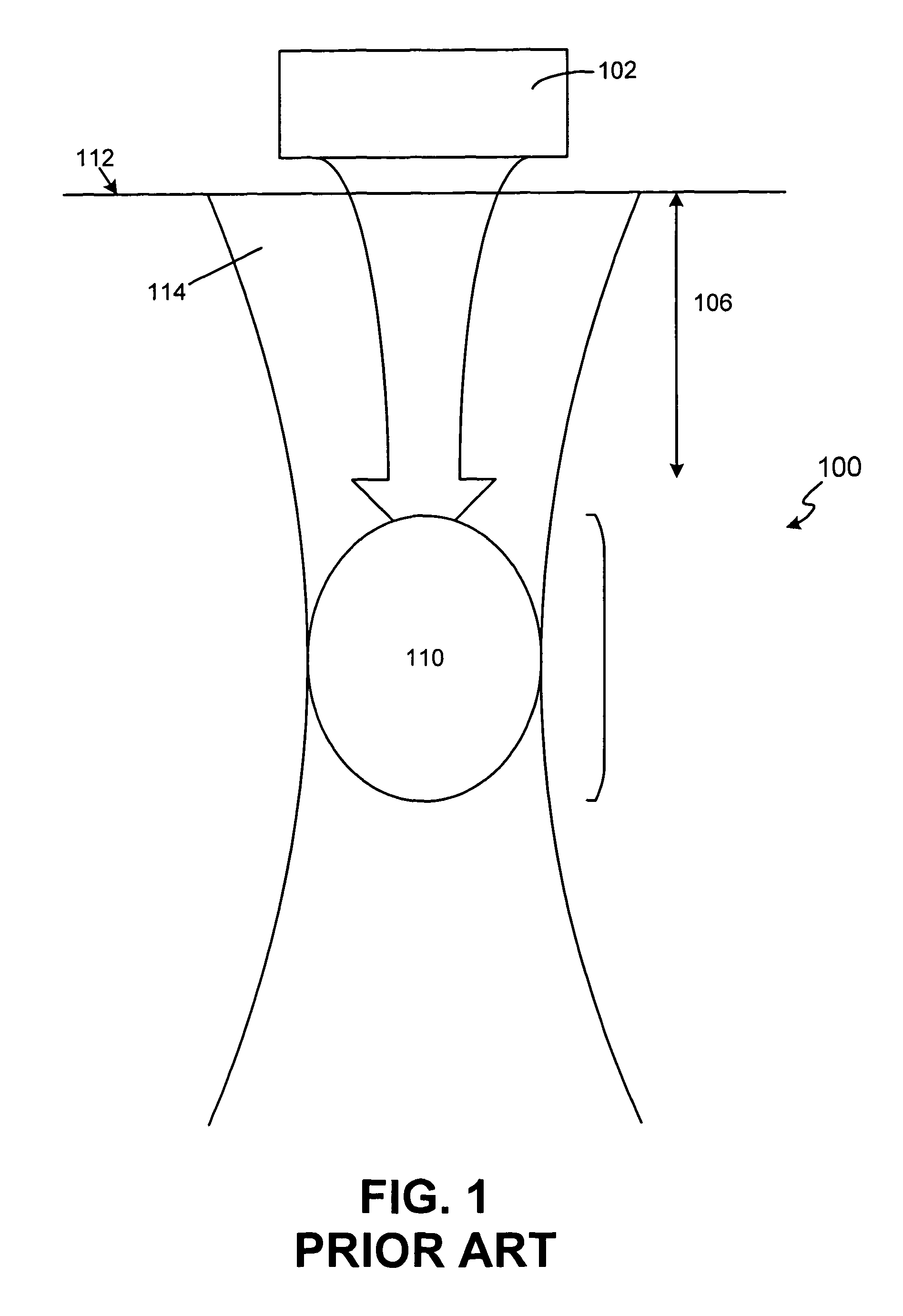
Another undesirable side effect of low-frequency therapy is that the acoustic energy must pass through intervening tissue layers before reaching the desired deep treatment area.
This causes the focal spot size to widen, making it difficult to control the location of the focal spot.

Method used


Image

  • System and method for variable depth ultrasound treatment
  • System and method for variable depth ultrasound treatment
  • System and method for variable depth ultrasound treatment

Examples


Embodiment Construction

[0026]The present invention may be described herein in terms of various components and processing steps. It should be appreciated that such components and steps may be realized by any number of hardware components configured to perform the specified functions. For example, the present invention may employ various medical treatment devices, visual imaging and display devices, input terminals and the like, which may carry out a variety of functions under the control of one or more control systems or other control devices. In addition, the present invention may be practiced in any number of medical or treatment contexts and that the exemplary embodiments relating to a variable depth ultrasound treatment as described herein are merely a few of the exemplary applications for the invention. For example, the principles, features and methods discussed may be applied to any medical or other tissue or treatment application. In accordance with various aspects of the present invention, a non-in...


PUM


Abstract

A non-invasive variable depth ultrasound treatment method and system comprises a variable depth transducer system configured for providing ultrasound treatment to a patient. An exemplary variable depth transducer system can comprise a transducer configured to provide treatment to more than one region of interest, such as between a deep treatment region of interest and a superficial region of interest, and / or a subcutaneous region of interest. The variable depth transducer can comprise a transduction element having a piezoelectrically active layer, matching layers and / or other materials for generating radiation or acoustical energy. The variable depth transducer may be configured to operate at moderate frequencies within the range from approximately 750 kHz to 20 MHz or more. In addition, the transduction element may be configured with a variable depth device comprising one or more materials configured to allow for control and focusing / defocusing of the acoustic energy to more than one region of interest.

Description

FIELD OF INVENTION[0001]This invention generally relates to an ultrasound system, and more particularly, to a method and system for variable depth ultrasound treatment.BACKGROUND OF THE INVENTION[0002]Many conventional applications of therapeutic ultrasound have employed low frequency transducers. These transducers have operational frequencies that typically range from 500 kHz to 1.5 MHz. Such low frequency transducers are often preferred because they allow for acoustical energy to be focused deep into the body, without harming the overlying tissue structures.[0003]A conventional application of non-invasive therapeutic ultrasound using a low frequency transducer is depicted in FIG. 1. A conventional therapeutic system 100 comprises a transducer 102 that uses low frequency energy to treat a deep treatment region 110. Deep treatment region 110 is located at a deep depth 106 below a superficial region 112, e.g., tissue layers and structures, and a subcutaneous region 114 of a patient. ...

Claims


Application Information

Patent Timeline
Patent Type & Authority Patents(United States)
IPC IPC(8): A61B17/22
CPCA61N7/00A61B19/2203A61B2017/22024A61B2017/22028A61N2007/0095A61N2007/0065A61N2007/0069A61N2007/0073A61B34/30
Inventor BARTHE, PETER G.SLAYTON, MICHAEL H.
Owner GUIDED THERAPY SYSTEMS LLC
Learn More