Hydraulic transmission ultrasonic transducing device

A technology of hydraulic transmission and energy conversion device, which is applied in the direction of fluid using vibration, etc., which can solve the problems of low energy conversion efficiency, complex structure, and large size, and achieve the effect of simple structure, high energy density, and fast response speed

Active Publication Date: 2015-04-15
HARBIN INST OF TECH
View PDF4 Cites 0 Cited by
  • Summary
  • Abstract
  • Description
  • Claims
  • Application Information

AI Technical Summary

Problems solved by technology

[0005] In order to solve the problems of complex structure, large size, low energy conversion efficiency and too small sound power of traditional transducers, the present invention further proposes a hydraulically driven ultrasonic transducer

Method used


Image

  • Hydraulic transmission ultrasonic transducing device
  • Hydraulic transmission ultrasonic transducing device
  • Hydraulic transmission ultrasonic transducing device

Examples


specific Embodiment approach 1

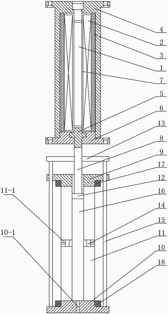
[0009] Specific implementation mode one: combine figure 1 Describe this embodiment, a hydraulically driven ultrasonic transducer device described in this embodiment includes a GMM rod 1, a drive coil 2, a permanent magnet 3, a transducer housing 4, a first prop 5, a top cover 6 and a magnetizer 7. The GMM rod 1 is inserted into the transducer housing 4, the driving coil 2 and the permanent magnet 3 are sequentially set on the GMM rod 1 from the inside to the outside, and the driving coil 2 and the permanent magnet 3 are located on the outer wall of the GMM rod 1 and Between the inner side walls of the transducer housing 4, the top cover 6 is sealed and connected to the opening of the transducer housing 4, and the upper end of the first top column 5 passes through the through hole in the middle of the top cover 6 and the end surface of one end of the GMM rod 1 contact, the gap between the driving coil 2 and the outer wall of the GMM rod 1 is filled with a magnetic conductor 7, ...

specific Embodiment approach 2

[0010] Specific implementation mode two: combination figure 1 To illustrate this embodiment, an O-ring is provided on the outer wall of the first piston 12 of the hydraulic transmission ultrasonic transducer device described in this embodiment, and an O-ring is respectively provided on the outer wall of each second piston 14. type sealing ring. Other components and connections are the same as those in the first embodiment.

specific Embodiment approach 3

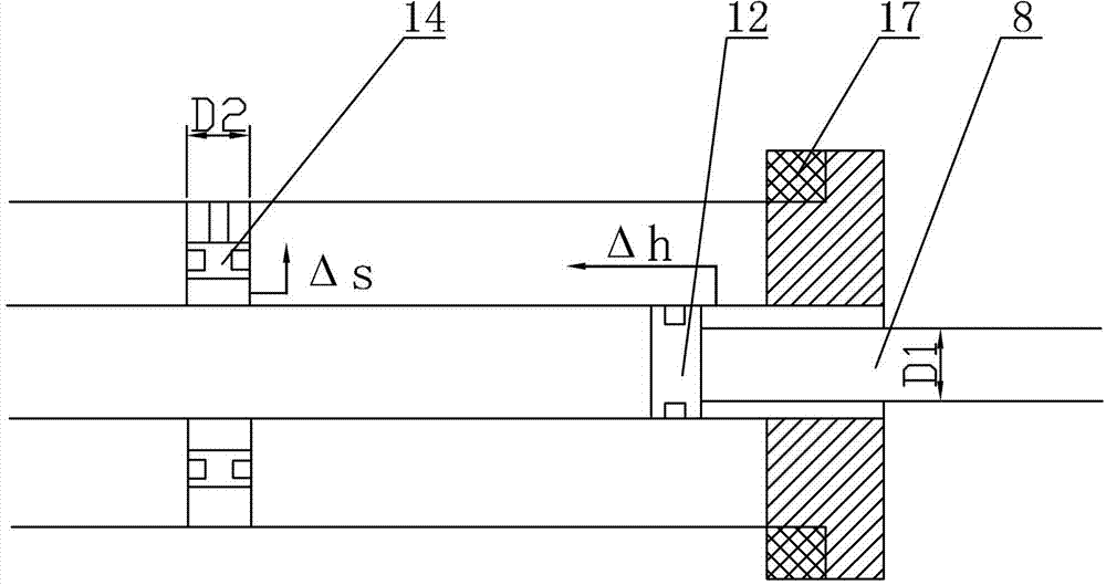
[0011] Specific implementation mode three: combination figure 1 To illustrate this embodiment, the lower upper end cover 9 of the hydraulic transmission ultrasonic transducer device described in this embodiment is provided with an upper end plate 17 on the outer side wall of the boss on the lower surface of the lower end cover 10, and on the outer side wall of the upper boss on the upper surface of the lower end A lower end plate 18 is provided in the suit.

[0012] Other components and connections are the same as those in the first embodiment.


PUM


Abstract

The invention discloses a hydraulic transmission ultrasonic transducing device, and relates to a transducing device, in particular to the hydraulic transmission ultrasonic transducing device, in order to solve the problems of complex structure, huge size, low energy conversion efficiency and small acoustic power of the conventional transducer. According to the transducing device, a supporting plate, an upper end cover and a lower end cover are sequentially arranged from top to bottom; the lower end cover is connected with the supporting plate through a plurality of pull rods; the upper end cover is connected with the lower end cover through a hydraulic cylinder; the lower surface of the upper end cover, the upper surface of the lower end cover and a cavity of the hydraulic cylinder form a closed cavity; the lower end of a second support pillar penetrates through the supporting plate and the upper end cover from top to bottom in sequence to be arranged in the cavity; the upper end of the second support pillar is connected with the lower end of a first support pillar; a first piston is connected with the lower end of the second support pillar; the outer side wall of the hydraulic cylinder is symmetrically provided with two through holes; a second position is arranged in each through hole, the lower bottom surface of the lower end cover is provided with an oil injection through hole; and the cavity is filled with hydraulic oil. The device is used for the field of mechanical engineering.

Description

technical field [0001] The invention relates to a transducer device, in particular to a hydraulic transmission ultrasonic transducer device. Background technique [0002] In recent years, with the rapid development of new functional materials—rare earth giant magnetostrictive materials (GMM), due to their excellent characteristics such as large magnetostrictive strain, high magnetic-machine coupling coefficient, fast response speed, and high energy density, they have been used in electromechanical Fields show good application prospects. [0003] For this reason, the wide application of fully utilizing the working characteristics of this new type of functional material as an output vibration force and displacement-vibration source (GMA) has attracted a lot of theoretical and analytical research at home and abroad. However, the research on giant magnetostrictive transducers applied to underwater, which converts the axial vibration along the GMM rod generated by the vibration ...

Claims


Application Information

Patent Timeline
Patent Type & Authority Patents(China)
IPC IPC(8): B06B1/08
Inventor 申岩
Owner HARBIN INST OF TECH
Why Eureka
Try Eureka