Megahertz-level wide-beam high-power transceiver integrated sound array

A wide-beam, high-power technology, applied in the field of megahertz wide-beam high-power transceiver integrated sound array, can solve the problems of increased directivity of the transmitting array, narrow transmitting beam, and increasing sound waves, etc., to improve the signal-to-noise ratio of the received signal, The effect of increasing the energy of the echo signal and increasing the working distance

Active Publication Date: 2022-02-01
NAVAL UNIV OF ENG PLA
View PDF3 Cites 0 Cited by
  • Summary
  • Abstract
  • Description
  • Claims
  • Application Information

AI Technical Summary

Problems solved by technology

One is that the frequency of megahertz-level sound waves is very high, and the beam of the emission array is very narrow. At this time, the propagation loss of sound waves in water is large, resulting in short propagation distances. Therefore, it is difficult to increase the distance between the sound array and the target to increase the sound wave irradiation surface. The purpose of this is to make the emitted sound waves not completely cover the underwater target with a certain volume, which will affect the measurement and analysis of its echo characteristics; the second is that the emission power of the underwater acoustic emission transducer is related to the size of its radiation surface. In order to enhance the echo signal, the radiation surface must be increased, but this will lead to an increase in the directivity of the emission array, making the emission beam narrower, making it difficult for sound waves to fully cover the target surface
Therefore, it is difficult for the currently developed megahertz-level acoustic array to simultaneously meet the requirements of the three index parameters of transmission frequency, beam width, and radiation power, and thus cannot meet the requirements for the measurement of VHF echo characteristics of underwater targets.

Method used


Image

  • Megahertz-level wide-beam high-power transceiver integrated sound array
  • Megahertz-level wide-beam high-power transceiver integrated sound array
  • Megahertz-level wide-beam high-power transceiver integrated sound array

Examples


Embodiment Construction

[0016] The present invention will be further described in detail below in conjunction with the accompanying drawings and specific embodiments to facilitate a clear understanding of the present invention, but they do not limit the present invention.

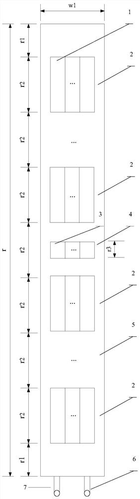
[0017] Such as figure 1 As shown, the present invention provides a megahertz-level wide-beam high-power transceiver integrated acoustic array, which is characterized in that: it includes a transmitting array, a receiving array, a signal transmission line, and a package body, and the transmitting array receives the acoustic signal from the signal transmission line and Transmit megahertz-level, wide-beam, high-power VHF acoustic signals to underwater targets, and the receiving array is used to receive reflected echoes from underwater targets beyond 7m and send the reflected echo signals to the signal transmission line. The emission array of the patent of the present invention is composed of a plurality of emission groups 2, and the ...


PUM


Abstract

The invention provides a megahertz-level wide-beam high-power integrated acoustic array, which is characterized in that it includes a transmitting array, a receiving array, a signal transmission line, and a packaging body, and the transmitting array receives the acoustic signal from the signal transmission line and transmits the acoustic wave signal to the target in the water. Transmit megahertz-level, wide-beam, high-power very high-frequency sound wave signals, the receiving array is used to receive the reflected echoes of targets in the water and send the reflected echo signals to the signal transmission line; multiple transmitting transducers form a transmitting group , a plurality of identical emission groups are distributed side by side to form a emission array; the receiving array is composed of a plurality of single receiving transducer sheets, and the number of receiving transducer sheets is consistent with the number of emitting transducer sheets forming a transmitting group; The signals between each transmitting transducer sheet and each emitting group are connected in parallel; the signals between the single receiving transducer sheets are connected in parallel. The patented invention has multiple functions and compact structure, can emit megahertz-level sound waves, and can receive reflected echoes from underwater targets.

Description

technical field [0001] The patent of the invention belongs to the field of transducers, and specifically relates to a megahertz-level wide-beam high-power transceiver integrated sound array. Background technique [0002] The echo characteristics of underwater targets in the megahertz frequency band are widely used in research fields such as target imaging and underwater acoustic simulation measurement. The currently developed megahertz-level sound arrays have obvious deficiencies in the following aspects. One is that the frequency of megahertz-level sound waves is very high, and the beam of the emission array is very narrow. At this time, the propagation loss of sound waves in water is large, resulting in short propagation distances. Therefore, it is difficult to increase the distance between the sound array and the target to increase the sound wave irradiation surface. The purpose of this is to make the emitted sound waves not completely cover the underwater target with a ...

Claims


Application Information

Patent Timeline
Patent Type & Authority Patents(China)
IPC IPC(8): G01S7/521G01S7/534
CPCG01S7/521G01S7/534
Inventor 程广利杜奎卢建斌于莹
Owner NAVAL UNIV OF ENG PLA
Why Eureka
Try Eureka