Automated apparatus and process for the controlled shutdown and start-up for a wastewater treatment system

a wastewater treatment system and automatic technology, applied in the direction of filtration separation, specific water treatment objectives, separation processes, etc., can solve the problems of significant fresh water volume, significant acquisition and discharge cost, shutdown of wastewater treatment system,

Inactive Publication Date: 2010-11-02
WATER SOLUTIONS TECH LLC
View PDF2 Cites 0 Cited by
  • Summary
  • Abstract
  • Description
  • Claims
  • Application Information

AI Technical Summary

Benefits of technology

[0013]The method includes terminating the influent flow of wastewater to be treated to the water input of the wastewater treatment system. This may be performed manually or automatically, depending upon the source of the wastewater and the treatment system. Clean water effluent is pumped from the effluent external tank to the water input. A sufficient volume of clean water effluent is passed through the wastewater treatment system to move existing wastewater through the system so it can be completely treated. This purges the wastewater treatment system and fills the treatment system with clean water effluent. The wastewater treatment system may then be safely shut down.
[0018]One useful advantage of the apparatus and method described herein is the ability to shut down a part-time wastewater treatment system without the need for external fresh water. The apparatus and method are self-contained.

Problems solved by technology

Of greater challenge is the shutdown of the wastewater treatment system during periods of no influent wastewater flow.
This solution, however, requires a significant volume of fresh water to purge the system.
Obtaining the needed fresh water represents a significant acquisition and discharge cost.

Method used


Image

  • Automated apparatus and process for the controlled shutdown and start-up for a wastewater treatment system
  • Automated apparatus and process for the controlled shutdown and start-up for a wastewater treatment system
  • Automated apparatus and process for the controlled shutdown and start-up for a wastewater treatment system

Examples


example 1

[0040]The following non-limiting example is one of many possible implementations of the apparatus and method within the scope of the present invention.

[0041]An operator, timer, control system, or other means determines that the water treatment system is to be shut down. The system may be prepared to be shut down by the following sequence of events:

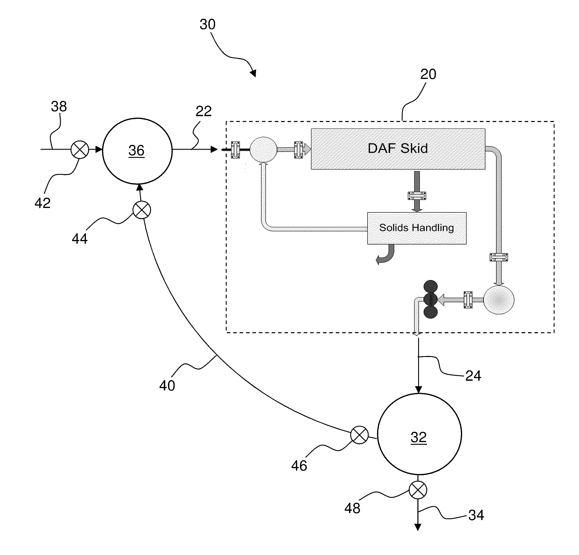
[0042]Effluent external tank 32 is preferably previously filled with clean water effluent from the water outlet 24. If necessary, the clean water effluent is treated to render is substantially free of pathogens.

[0043]In the event effluent external tank 32 has not been filled to a minimum capacity, additional clean water effluent may be diverted to this tank from the water outlet 24 while wastewater processing continues. In some embodiments, the minimum capacity is at least two system capacity volume of the treatment system.

[0044]The flow of influent wastewater 38 to buffer tank 36 or water input 22 is terminated. Valve 42 may be closed. Th...


PUM

PropertyMeasurementUnit
capacity volumeaaaaaaaaaa

Abstract

An apparatus and method for cleaning and shutting down a part-time wastewater treatment system is disclosed. The wastewater treatment system has a water input to receive an influent flow of wastewater to be treated, a water output to discharge treated clean water effluent, and a water treatment capacity volume. An effluent external tank receives the clean water effluent and has a size greater than or equal to the capacity volume. Influent flow of wastewater is terminated. Clean water effluent is pumped through a fluid pathway from the effluent external tank to the water input. A sufficient volume of clean water effluent is passed through the wastewater treatment system to complete treatment of the wastewater within the wastewater treatment system, purge wastewater from the wastewater treatment system, and fill the wastewater treatment system with clean water effluent. The wastewater treatment system is thus prepared to be shut down.

Description

CROSS-REFERENCE TO RELATED APPLICATION[0001]This application claims the benefit of U.S. Provisional Patent Application 60 / 869,946, filed Dec. 14, 2006, which application is incorporated by reference.BACKGROUND OF THE INVENTION[0002]This invention relates to an automated apparatus and process for the controlled shutdown and start-up of a wastewater treatment system. The invention is particularly adapted for use with wastewater treatment systems that are not operated on a fulltime basis, but experience periods of inoperation.[0003]U.S. Federal Regulations set strict limitations for water discharged into the environment from Publicly Owned Treatment Works (POTW). Such requirements, and others like them, dictate the management and regulation of the wastewater discharge to the POTW facilities. To meet these requirements, industrial users are being required to install wastewater pretreatment plants. These pretreatment plants will typically reduce the biochemical oxygen demand (BOD), chemi...

Claims


Application Information

Patent Timeline
Patent Type & Authority Patents(United States)
IPC IPC(8): C02F1/00
CPCC02F1/24C02F2303/14
Inventor RUSNACK, MICHAEL R.ALLEN, STEPHEN D.
Owner WATER SOLUTIONS TECH LLC
Why Eureka
Try Eureka