Remote racking of horizontally displaceable circuit breakers

a technology of horizontal dislocation and circuit breakers, which is applied in the direction of air-break switches, high-tension/heavy-dress switches, electrical apparatuses, etc., can solve the problems of operator risk, object to be hurled through the air at high velocity, and serious injury or death

Active Publication Date: 2010-11-02
STEVENSON ROBERT L
View PDF3 Cites 23 Cited by
  • Summary
  • Abstract
  • Description
  • Claims
  • Application Information

AI Technical Summary

Benefits of technology

[0015]The force-transmitting member and the mounting member may be provided with cooperating positioning elements for positioning the force-transmitting member and the mounting member in a predetermined relative position. Additionally, the mounting member can be formed with a locking element for locking the force-transmitting member to the mounting member. The positioning elements are advantageously designed to prevent relative rotation of the force-transmitting member and the mounting member.

Problems solved by technology

An arc-flash occurs when current flows through the air between a conductor of the switchgear and ground, and such current flow can be accompanied by extremely high temperatures and pressures which, in turn, can cause objects to be hurled through the air at high velocity.
The high temperatures and pressures can result in serious injury or death as can any flying objects produced by these temperatures and pressures.
Since an arc-flash can occur during both racking-in and racking-out, the operator is at risk while performing these procedures.
However, this system is designed solely for vertically racked circuit breakers.

Method used


Image

  • Remote racking of horizontally displaceable circuit breakers
  • Remote racking of horizontally displaceable circuit breakers
  • Remote racking of horizontally displaceable circuit breakers

Examples


Embodiment Construction

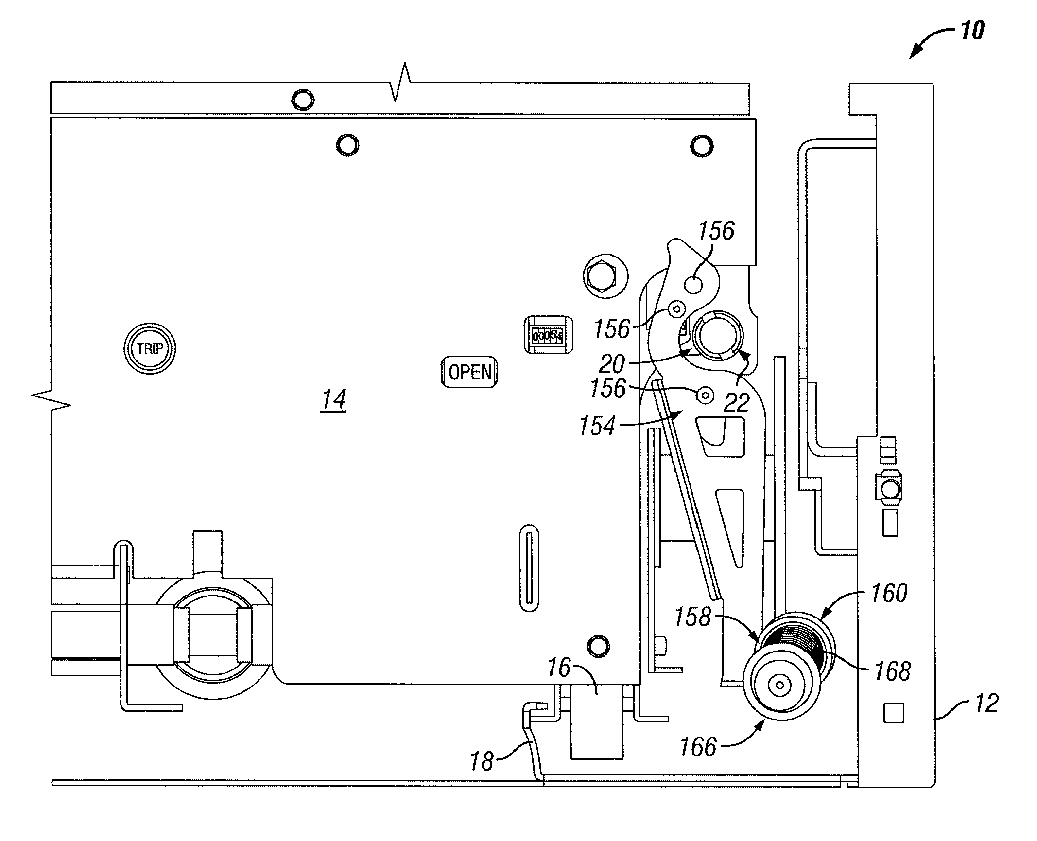
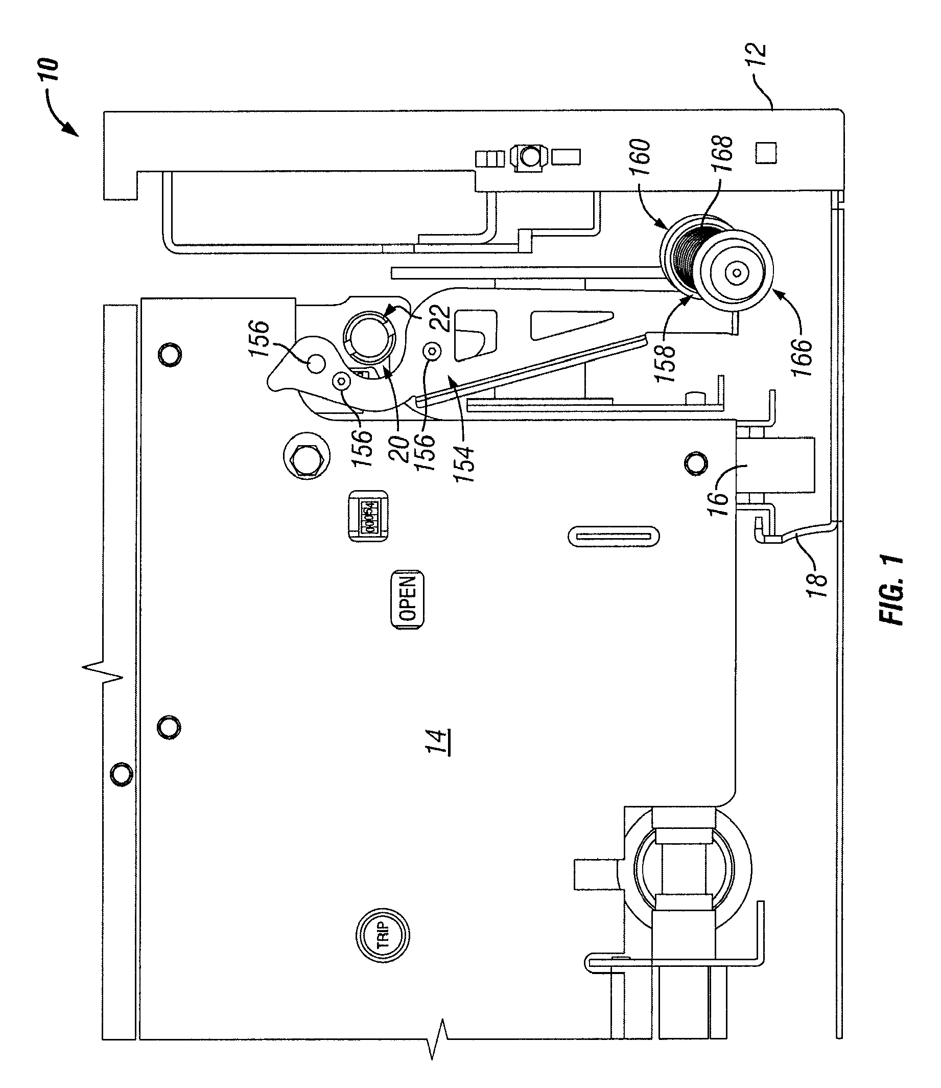
[0050]FIG. 1 shows a segment of conventional electric switchgear. The switchgear consists of one or more banks of identical cells, and FIG. 1 illustrates a section of one such cell. The cell of FIG. 1 is identified by the numeral 10 and includes a cubicle or cabinet 12 which houses a circuit breaker 14. The circuit breaker 14 is provided with non-illustrated terminals and is movable back-and-forth along a horizontal surface S between a “connect” position and a “disconnect” position. The circuit breaker terminals engage non-illustrated fixed terminals of the switchgear when the circuit breaker 14 is in the “connect” position, and the circuit breaker terminals are out of engagement with the fixed terminals when the circuit breaker 14 is in the “disconnect” position. The fixed switchgear terminals are located inside the cubicle 12.

[0051]Consistent with accepted terminology, the term “racking-in” in the following description will be understood to mean displacement of the circuit breaker...


PUM


Abstract

A system for remotely racking a horizontally movable circuit breaker includes a motor as well as a transmission connectible to the motor and to a racking screw for moving the circuit breaker. The system further includes a mounting bracket for holding the transmission and a controller for controlling the motor from a location remote from the circuit breaker.

Description

FIELD OF THE INVENTION[0001]The invention relates to the servicing of electrical switchgear.DESCRIPTION OF THE PRIOR ART[0002]Low-voltage and medium-voltage electrical switchgear typically includes one or more banks of circuit breakers. The circuit breakers are housed in individual cubicles provided with doors, and each circuit breaker is equipped with terminals. Each circuit breaker is movable independently of the others between a “connect” position in which the circuit breaker terminals engage corresponding fixed terminals of the switchgear and a “disconnect” position in which the circuit breaker terminals are out of engagement with the fixed switchgear terminals. Movement of a circuit breaker from the “disconnect” position to the “connect” position is known as “racking-in” while movement of the circuit breaker from the “connect” position to the “disconnect” position is known as “racking-out”.[0003]Two types of electrical switchgear are in existence. The circuit breakers of one ty...

Claims


Application Information

Patent Timeline
Patent Type & Authority Patents(United States)
IPC IPC(8): H01H33/42H01H9/20H01H9/24
CPCH02B11/127
Inventor STEVENSON, ROBERT L.
Owner STEVENSON ROBERT L
Why Eureka
Try Eureka