Micro lens array unit having at least one of first and second micro lens arrays movable for changing the effective focal length of the micro lens array unit and liquid crystal display projection device using same

a micro lens array and array unit technology, applied in the field of projection technology, can solve the problems of affecting the brightness of the lens array unit, and affecting the ability to achieve both satisfactory brightness and desirable contras

Inactive Publication Date: 2010-11-02
HON HAI PRECISION IND CO LTD
View PDF3 Cites 3 Cited by
  • Summary
  • Abstract
  • Description
  • Claims
  • Application Information

AI Technical Summary

Benefits of technology

[0004]LCD projectors, especially 3LCD projectors, are capable of reproducing bright, natural images that are easy on eyes, and therefore pleasant to watch. These LCD projectors typically employ an LCD panel (three in 3LCD type) for image generation, and the brightness of the reproduced images is mainly determined by the aperture ratio of the LCD panel (the greater the aperture ratio, the higher the brightness). A MLA unit is normally used to increase the brightness. The MLA includes a number of micro lenses, each of which is dedicated to focus incident light into the opening of respective pixels of the LCD panel, thereby increasing the aperture ratio of the LCD panel. However, as the incident light is concentrated by the MLA, peripheral aberrations such as distortion may become greater. In other words, the MLA may decrease the contrast of the reproduced images. It has been challenging to achieve both satisfactory brightness and desirable contrast.

Problems solved by technology

However, as the incident light is concentrated by the MLA, peripheral aberrations such as distortion may become greater.
It has been challenging to achieve both satisfactory brightness and desirable contrast.

Method used


Image

  • Micro lens array unit having at least one of first and second micro lens arrays movable for changing the effective focal length of the micro lens array unit and liquid crystal display projection device using same
  • Micro lens array unit having at least one of first and second micro lens arrays movable for changing the effective focal length of the micro lens array unit and liquid crystal display projection device using same
  • Micro lens array unit having at least one of first and second micro lens arrays movable for changing the effective focal length of the micro lens array unit and liquid crystal display projection device using same

Examples


Embodiment Construction

[0011]Embodiments of the present MLA unit and LCD projection device will now be described in detail with reference to the drawings.

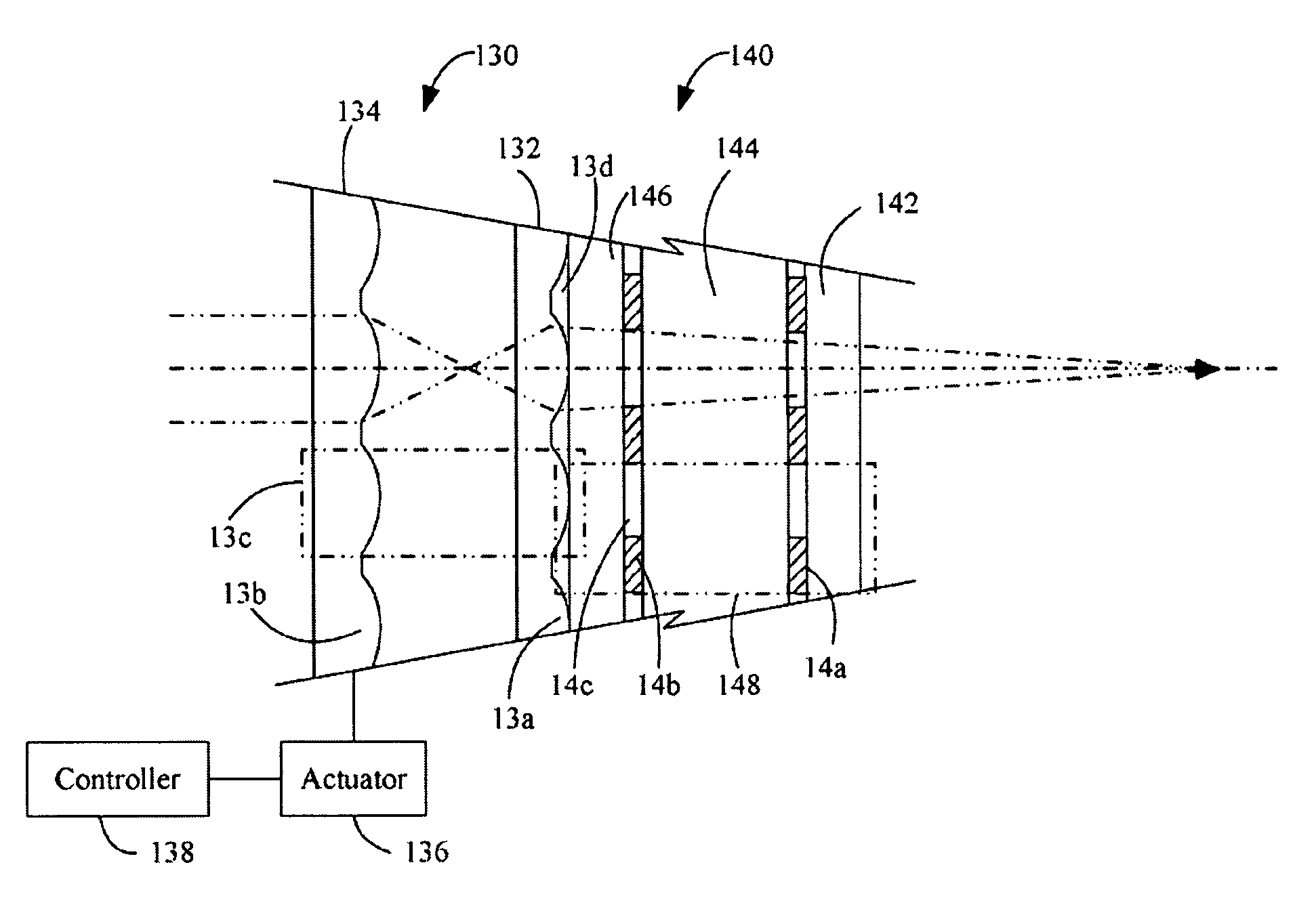
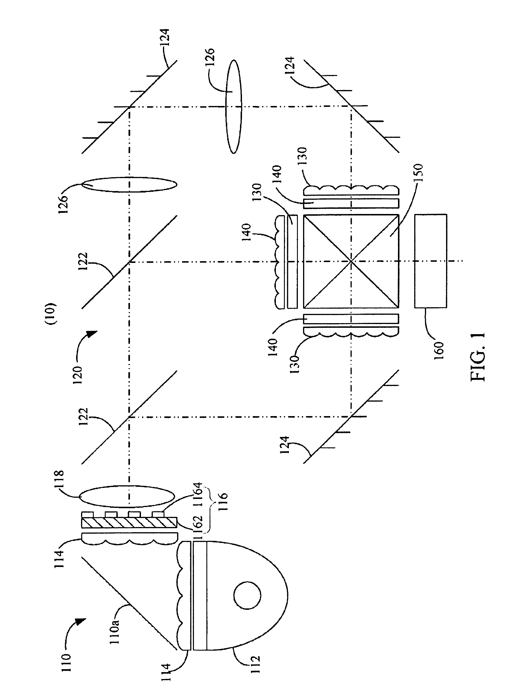
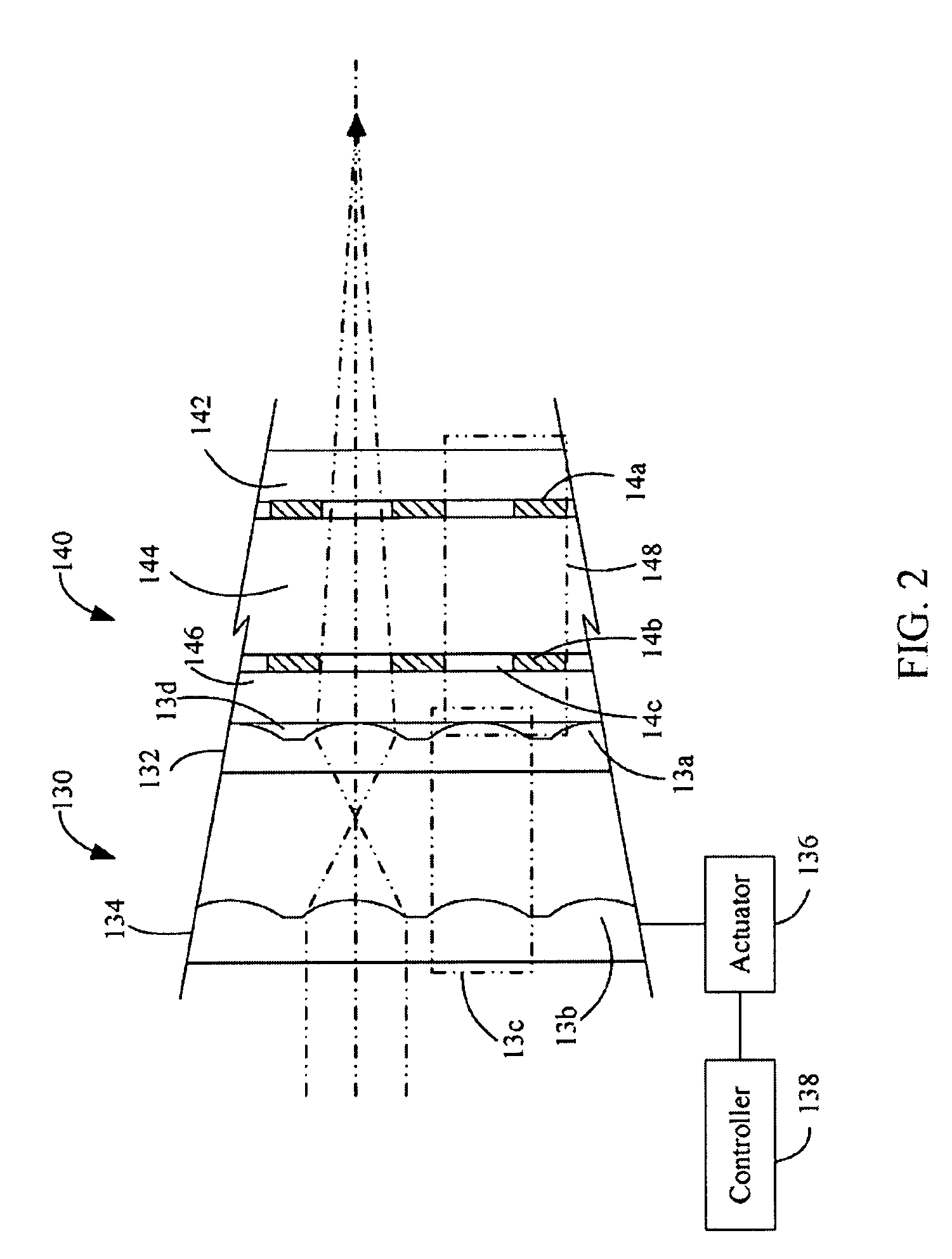
[0012]Referring to FIG. 1, a 3LCD projection device 10, according to an exemplary embodiment, includes an illumination unit 110, a color splitting system 120, three MLA units 130, three LCD panels 140, a prism 150, and a projection lens 160. The illumination unit 110 is configured to provide illumination. The color splitting system 120 is placed in the path of the light from the illumination unit 110 to separate the light into three beams of color light, e.g., red (R), green (G), and blue (B), and is configured to direct each beam of color light along a respective color channel / path. The three MLA units 130 and the three LCD panels 140 are set in the paths of the three beams of color light, respectively, in the color splitting system 120. The MLA units 130 are configured to increase the aperture ratio of the three LCD panels 140 respectively. The LCD pan...


PUM


Abstract

An exemplary MLA unit for use in a projection device is disclosed. The projection device includes an LCD panel. The LCD panel includes a number of pixels each having an opening. The MLA unit includes a first MLA, and a second MLA. The first MLA includes a number of first micro lenses each configured for focusing incident light into the opening of a respective pixel of the LCD panel. The second MLA includes a number of second micro lenses each aligned with a respective first micro lens of the first MLA so as to form a micro lens system. The second MLA is movable so as to change the effective focal length of the lens systems.

Description

BACKGROUND[0001]1. Technical Field[0002]The invention relates to projection technology and, in particular, relates to a micro lens array (MLA) unit used in a liquid crystal display (LCD) projection device, and an LCD projection device.[0003]2. Description of the Related Art[0004]LCD projectors, especially 3LCD projectors, are capable of reproducing bright, natural images that are easy on eyes, and therefore pleasant to watch. These LCD projectors typically employ an LCD panel (three in 3LCD type) for image generation, and the brightness of the reproduced images is mainly determined by the aperture ratio of the LCD panel (the greater the aperture ratio, the higher the brightness). A MLA unit is normally used to increase the brightness. The MLA includes a number of micro lenses, each of which is dedicated to focus incident light into the opening of respective pixels of the LCD panel, thereby increasing the aperture ratio of the LCD panel. However, as the incident light is concentrated...

Claims


Application Information

Patent Timeline
Patent Type & Authority Patents(United States)
IPC IPC(8): H01L27/00
CPCG02B3/0062G02B15/14G03B21/14H04N9/3152H04N9/3197G02B1/02G03B21/208G02B15/142
Inventor HSU, CHIEN-WENWANG, PO-LINCHU, CHING-TECHOU, YU-SHAN
Owner HON HAI PRECISION IND CO LTD
Why Eureka
Try Eureka