Liquid crystal display device having direct backlight with an odd number of fluorescent lamps providing enhanced brightness at center of screen
a liquid crystal display device and fluorescent lamp technology, applied in the direction of illuminated signs, display means, instruments, etc., can solve the problems of increasing the power consumption of the tv, increasing the brightness irregularities of the backlight, increasing the power consumption of the backlight, etc., to achieve the effect of increasing the brightness at improving the brightness of the center of the screen, and being easy to assembl
- Summary
- Abstract
- Description
- Claims
- Application Information
AI Technical Summary
Benefits of technology
Problems solved by technology
Method used
Image
Examples
embodiment 1
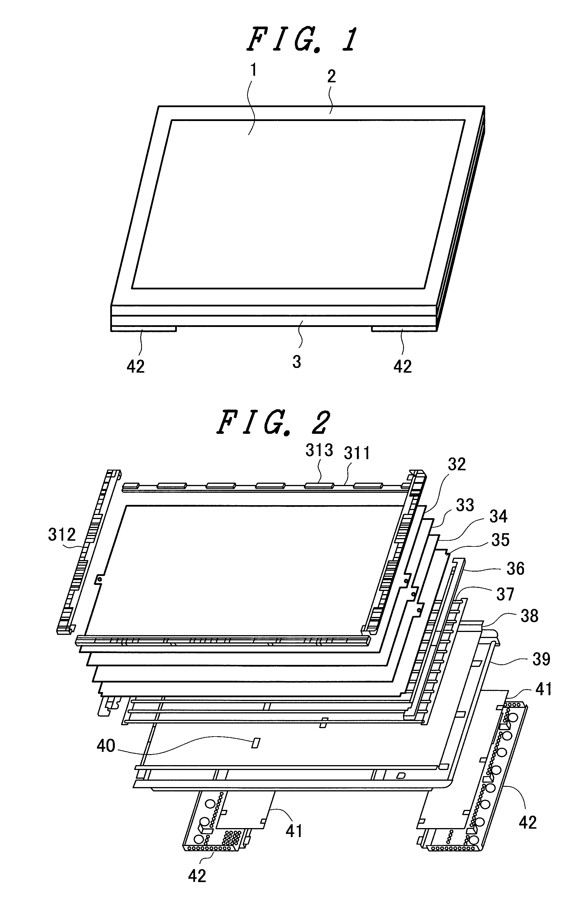
[0055]FIG. 1 is a schematic view of a liquid crystal display device. A liquid crystal display panel 1 is stored in the inside of a frame-shaped surface frame 2. The liquid crystal display panel 1 is constituted of a TFT substrate on which image signal lines, scanning lines, pixel electrodes, thin film transistors (TFT) and the like are formed, a counter substrate on which a color filter substrate and the like are formed, a lower polarizer adhered to the TFT substrate, and an upper polarizer adhered to the counter substrate. The liquid crystal display panel 1 is covered with a surface frame 2. In FIG. 1, only a display screen of the liquid crystal display panel 1 is shown.
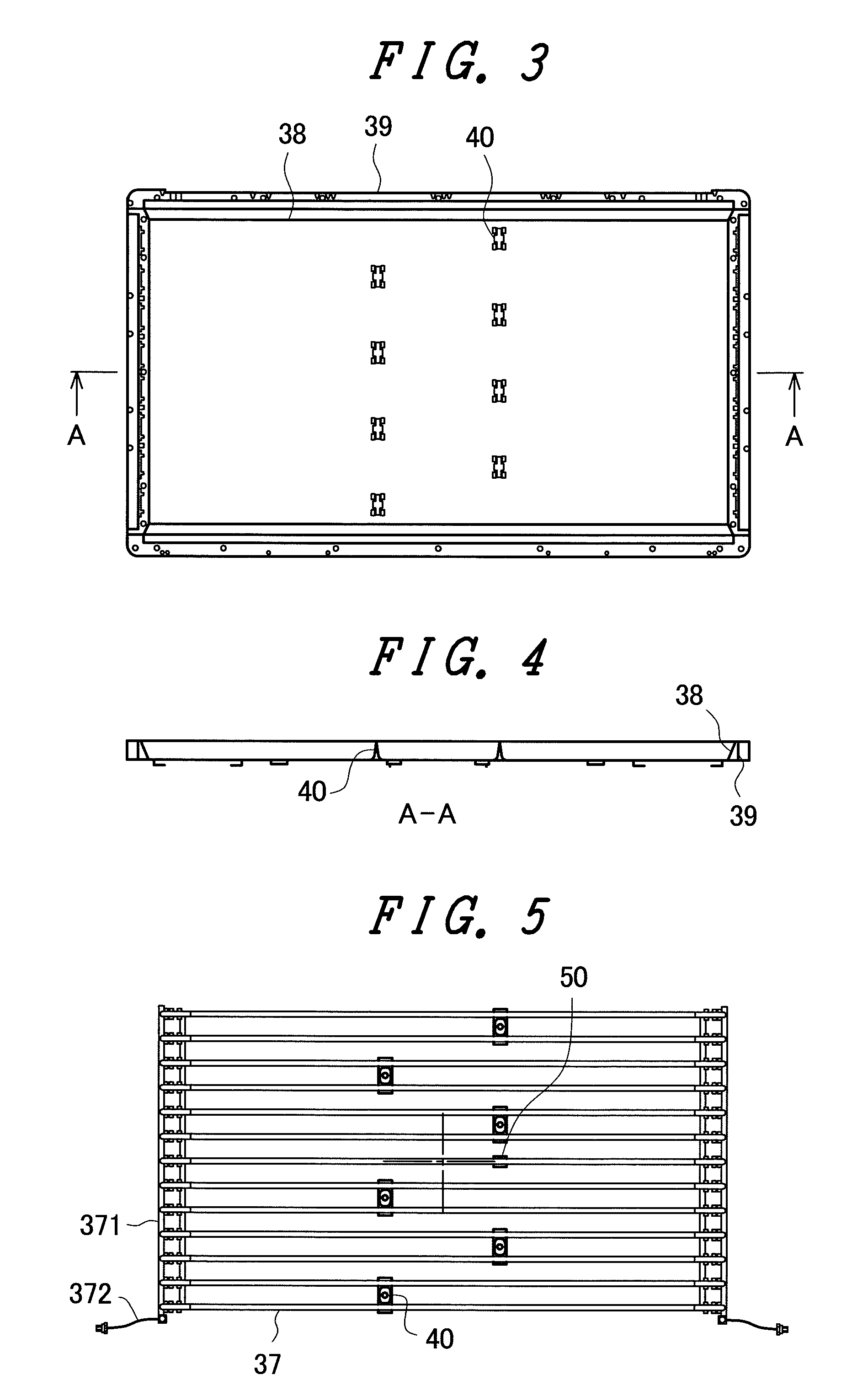
[0056]A backlight 3 is arranged behind the liquid crystal display panel 1. The liquid crystal display panel 1 changes over light from the backlight 3 for every pixel to form an image. For efficiently taking out the light toward the liquid crystal display panel 1, the backlight 3 is constituted of a light source such...
embodiment 2
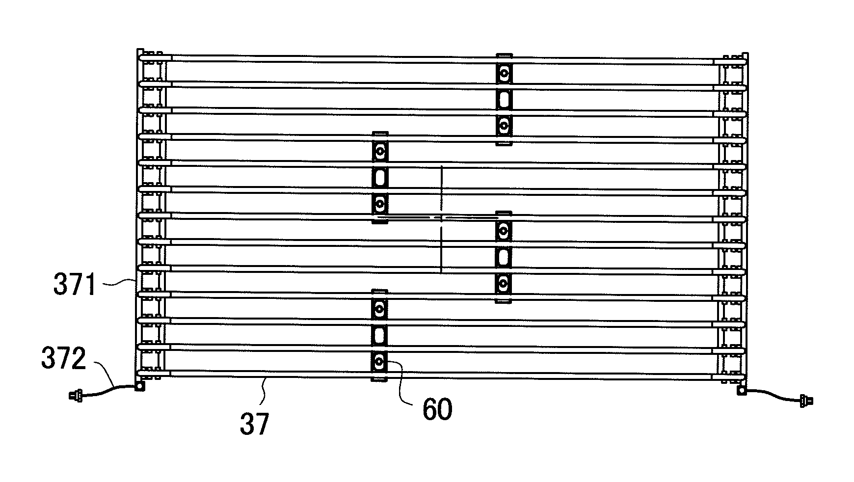
[0071]FIG. 9 is an arrangement view of fluorescent lamps 37 showing a second embodiment of the present invention. The constitution of a liquid crystal display device of this embodiment is substantially equal to the constitution of the liquid crystal display device of the embodiment 1 except for the arrangement of the fluorescent lamps 37. Also in this embodiment, the fluorescent lamps 37 are formed of an external electrode fluorescent lamp. Accordingly, it is unnecessary to provide a power source cable from an inverter for every fluorescent lamp, and a power source is supplied to external electrodes of the respective fluorescent lamps 37 via a fluorescent-lamp-use common electrode.
[0072]Also in this embodiment, the odd-number pieces of, that is, 13 pieces of fluorescent lamps 37 are used. Accordingly, it is possible to arrange the fluorescent lamp 37 at a center portion of a TV screen. The technical feature of this embodiment lies in that all of intermediate holders for supporting 1...
embodiment 3
[0074]FIG. 10 is an arrangement view of fluorescent lamps 37 showing a third embodiment of the present invention. The constitution of a liquid crystal display device of this embodiment is substantially equal to the constitution of the liquid crystal display device of the embodiment 1 except for the arrangement of the fluorescent lamps 37. Also in this embodiment, the fluorescent lamps 37 are formed of an external electrode fluorescent lamp. Accordingly, it is unnecessary to provide a power source cable from an inverter for every fluorescent lamp, and a power source is supplied to external electrodes of the respective fluorescent lamps 37 via a fluorescent-lamp-use common electrode.
[0075]Also in this embodiment, the odd-number pieces of, that is, 13 pieces of fluorescent lamps 37 are used. Accordingly, it is possible to arrange the fluorescent lamp 37 at a center portion of a TV screen. The technical feature of this embodiment lies in that the intermediate holders for supporting 13 p...
PUM
| Property | Measurement | Unit |
|---|---|---|
| thickness | aaaaa | aaaaa |
| thickness | aaaaa | aaaaa |
| shape | aaaaa | aaaaa |
Abstract
Description
Claims
Application Information
 - R&D
- Intellectual Property
- Life Sciences
- Materials
- Tech Scout
- Unparalleled Data Quality
- Higher Quality Content
- 60% Fewer Hallucinations
Browse by: Latest US Patents, China's latest patents, Technical Efficacy Thesaurus, Application Domain, Technology Topic, Popular Technical Reports.
© 2025 PatSnap. All rights reserved.Legal|Privacy policy|Modern Slavery Act Transparency Statement|Sitemap|About US| Contact US: help@patsnap.com


