
Radio-resource management system and method thereof, and management apparatus, base station and terminal to be employed for it

Active Publication Date: 2010-11-02
NEC CORP
View PDF24 Cites 19 Cited by
  • Summary
  • Abstract
  • Description
  • Claims
  • Application Information

AI Technical Summary

Benefits of technology

[0017]The objective of the present invention is to provide a radio-resource management system and a method thereof, a server, a base station and a terminal to be employed for it, and a program thereof that enable the radio resource, which is held in common, to be optim

Problems solved by technology

In this case, however, even though a traffic demand is remarkably less than forecasted in a network of a specific radio operator, and there exists the radio resource excessively, it is impossible to accommodate the other radio operator with its excess, whereby the problem exists that availability efficiency of the frequency goes down.
These kinds of the autonomous radio-resource management by the terminal or the radio base station are relatively easy of realization, whereas the problem exists that they do not always function as originally planned because there is restriction to information that can be mutually notified between the wireless networks of the plural operators having different operational policies, and also, because the effect can be expected only when almost all terminals and radio base stations correspond to the autonomous radio-resource management.
In this case, a plurality of the radio operators mutually hold the radio resource in common, and as a result, the interference of the radio occurs between the systems.
In the conventional autonomous radio-resource management technique, each radio operator is to alter the frequency channel of the radio base station, the transmitted power, the position of the radio base station, etc. so as to avoid the interference based on limited information that it can utilize; however optimal radio-resource allocation is not always made in the entire system having the plural operators brought together because information is limited.

Method used


Image

  • Radio-resource management system and method thereof, and management apparatus, base station and terminal to be employed for it
  • Radio-resource management system and method thereof, and management apparatus, base station and terminal to be employed for it
  • Radio-resource management system and method thereof, and management apparatus, base station and terminal to be employed for it

Examples


first embodiment

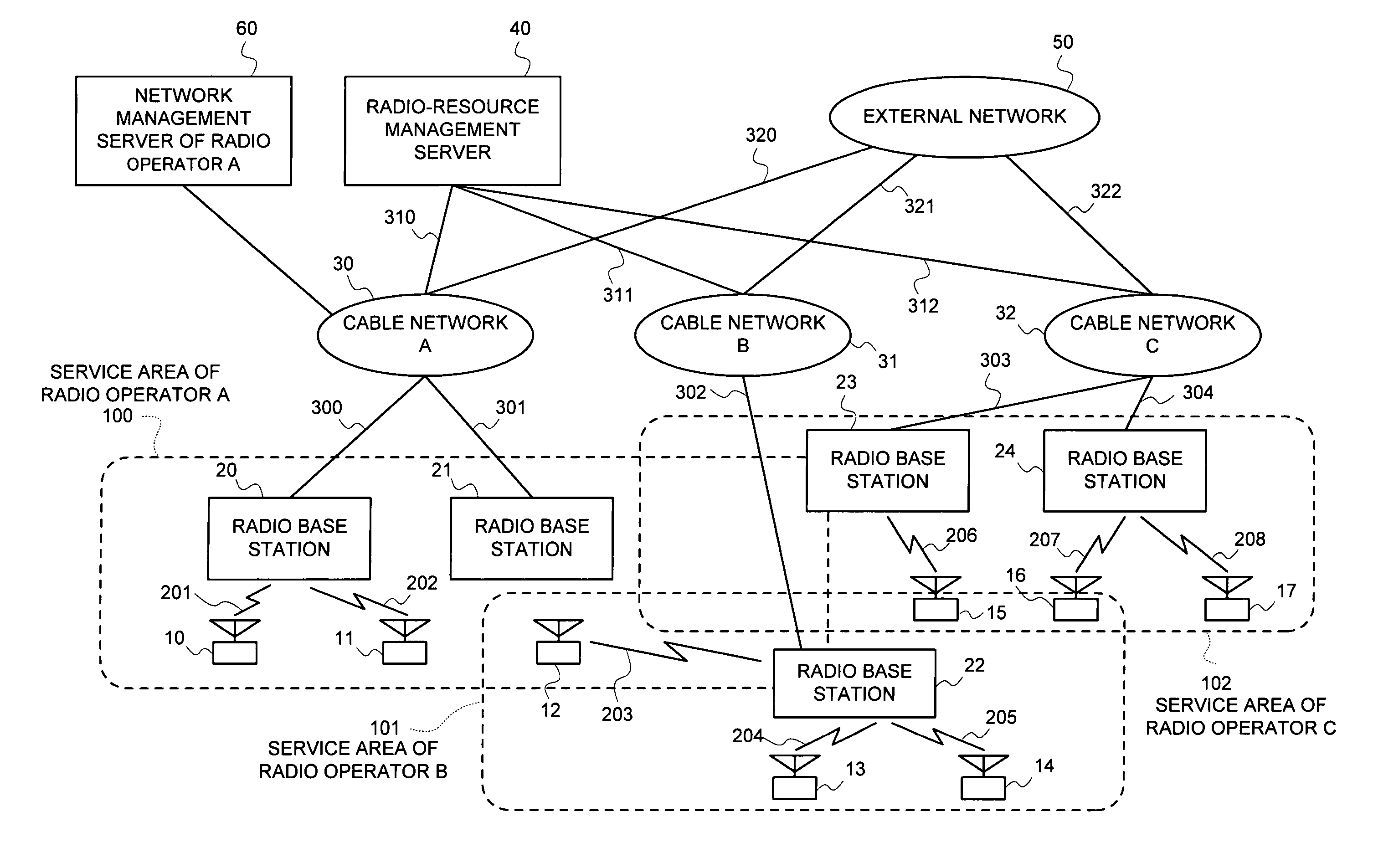
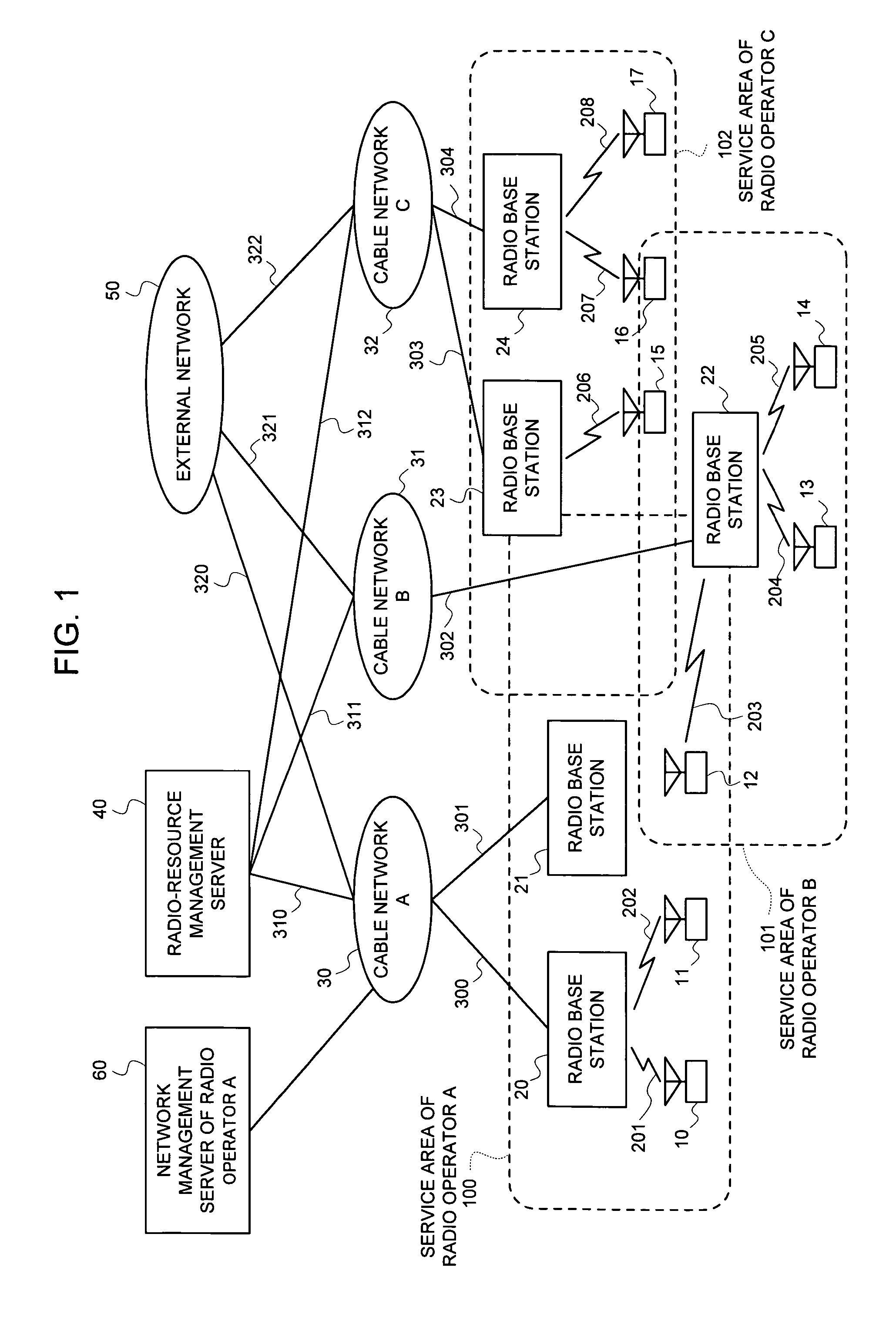
[0069]Hereinafter, embodiments of the present invention will be explained in details by referring to the accompanied drawings. In FIG. 1 is shown a configuration of the radio-resource management system in the present invention. A service area 100 of a radio operator A, a service area 101 of a radio operator B, and a service area 102 of a radio operator C exist in a partially-overlapped state, and a radio-resource management server 40 manages the radio resource in a unified manner that these three operators hold in common. Herein, assume that each of the operators mutually makes a contract for roaming with the other so that respective radio terminals can freely roam among these service areas 100 to 102 for continuing communication, and this roaming allows each of the service areas to interpolate the other. Also, each operator may employ the configuration having a network management server for an operator within the network (In FIG. 1, a network management server 60 of the radio opera...

third embodiment

[0126]In FIG. 17 is illustrated an operational flowchart of the radio terminal in the present invention. Also in this case, similarly, the value of the timer at the moment that the radio terminal notifies the link quality to the radio-resource management server is switched over in two stages; however a criterion for switching over is decided by a distribution value of the received level. In the event that a received-level distribution value Pd from the radio base station during communication falls below a fast-measured threshold Pd_th (step 445), fluctuation in the quality is regarded to be mild, and the measurement period T2 is set to be long (step 443). In the event that the distribution value Pd exceeded Pd_th, the measurement period T2 is set to be short once again (step 444). In addition, the similar control may be applied for the radio base station.

[0127]In such a manner, setting the notification period to be long during the time that the quality is in good state allows the qu...

sixth embodiment

[0141]For this, the process of restraining the current value Vi to Vi_max is performed in the radio-resource management server (step 807) in the event that the computed current price Vi exceeded the above upper limit value Vi_max (step 806). The other process is similar to that of FIG. 22.

[0142]Needless to say, the operational flow of each apparatus mentioned above is realized by pre-filing it as a program in a record medium such as a ROM to cause the CPU that is a computer to read it for execution.


PUM


Abstract

Terminals and base stations belonging to service areas 100 to 102 of plural radio operators periodically measure a radio-link quality and an availability ratio of a radio link to notify them to a radio-resource management server 40. The server 40 alters a frequency of the base station, and a transmitted-power quantity of the base station and the terminal based on these measured results to improve the radio-link quality, and reduces interference with a neighboring radio system. When a load is concentrated on a network of a specific radio operator, an instruction of handover is given to the terminal from the server 40 to realize a load distribution within the radio operator, and between the radio operators. When the server 40 detects excessive radio interference between the radio operators, it notifies occurrence of a fault, an interference quantity, a quantity of the transmitted power that the base station should attenuate, and the frequency that the base station should alter to the above radio operator that becomes an interference source.

Description

BACKGROUND OF THE INVENTION[0001]The present invention relates to a radio-resource management system and a method thereof, a management apparatus, a base station and a terminal to be employed for it, and a program thereof, and more particularly to a technique of managing a radio resource extending over networks of a plurality of radio operators in a wireless network such as public mobile communication by a cellular technique, and a wireless LAN.[0002]In a conventional wireless network, each radio operator installed radio base stations independently, and the radio resource such as a frequency channel that the radio base station and a radio terminal utilize, transmitted power of a radio link, and a transfer rate was managed independently operator by operator. In the event of the public mobile communication by the cellular technique, an exclusive right to the use of a frequency band is normally given to each operator as license, whereby no radio interference occurs between the operator...

Claims


Application Information

Patent Timeline
IPC IPC(8): H04B1/00H04L12/28H04B7/26H04W36/14
CPCH04W16/14H04W52/241H04W52/18H04W36/14H04W36/22H04W36/142H04W24/10H04W28/16H04W68/005
Inventor MATSUNAGA, YASUHIKO
Owner NEC CORP
Learn More