Insulated blocking panels and assemblies for I-joist installation in floors and ceilings and methods of installing same

a technology of i-joists and insulating blocks, which is applied in the direction of load-supporting braces, building roofs, building components, etc., can solve the problems of reducing insulation value and substandard installation quality, and achieves the effect of convenient installation and superior load distribution

Inactive Publication Date: 2010-11-09
SILPRO
View PDF28 Cites 13 Cited by
  • Summary
  • Abstract
  • Description
  • Claims
  • Application Information

AI Technical Summary

Benefits of technology

[0007]Therefore, there is needed an improved insulation system for I-joist assemblies. The present invention fulfills this need, while providing multiple benefits comprising ease and speed of installation and assembly strength and stability, as is discussed in the following disclosure.SUMMARY OF THE INVENTION
[0010]The insulating portion may be a block or one or more layers, herein called a “board” for convenience, that is preferably substantially rigid so that handling and placement of the insulated blocking panels is convenient, certain, and consistent. The insulating portion may be selected, for example, from various foams including open and closed cell foams, polystyrenes, polyisocyanurate, polymethanes, soybean-based foams / polymers, synthetic resins and polymers, fibrous materials such as spun fiberglass, cellulose, treated wood fibers, rock-wool, compressed straw or other agricultural or natural products, and / or any other appropriate insulating materials either separately, in combination, in mixtures, in layers, and / or in composite forms. While it is preferred that the insulating portion be substantially rigid, there may also be embodiments that utilize more flexible insulating portions and rely on the structural portion(s) (and especially the preferred vertical structural panel(s) discussed below) to provide the rigidity for said ease, certainty and consistency in handling and installation as well as to provide the rigidity for structural enhancement of the assemblies. Preferably, the preferred insulation material(s) are formed or attached to each other for forming a block, sheet, or panel of such a thickness that it is generally and substantially rigid and has a high R value.
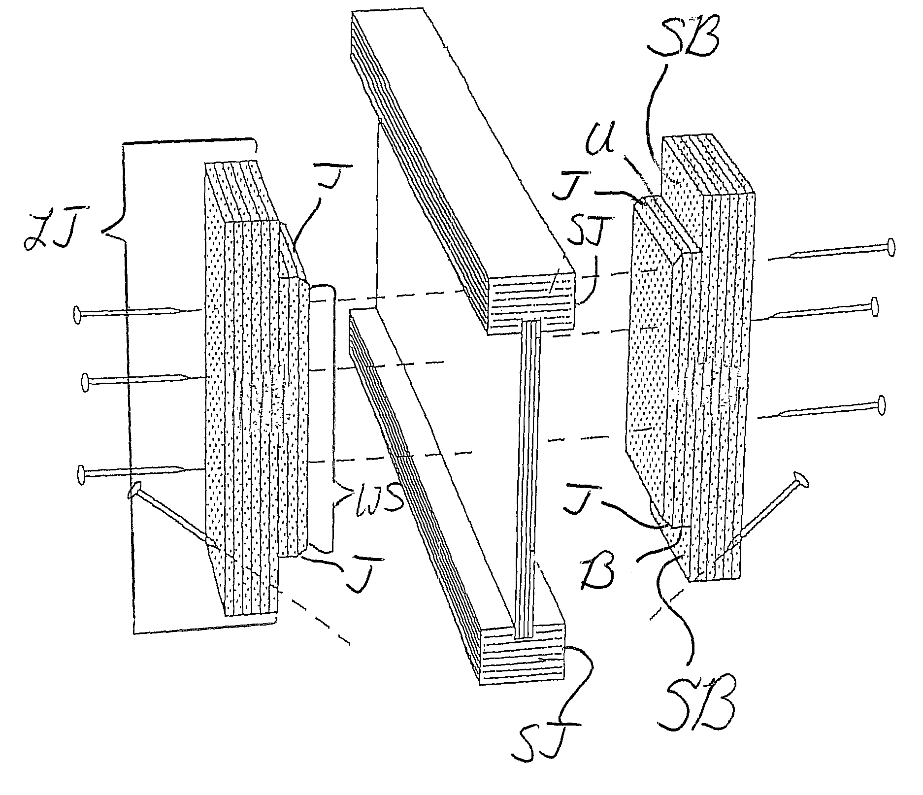
[0014]The insulated blocking panel preferably has ends that are each formed to match the side profile of the I-joist. This matching side profile may be formed by the insulating portion and structural portion extending to substantially fill the area near the I-joist web between the I-joist flanges. Thus, the matching side profile may be formed by the preferred insulating portion and the vertical structural panel(s), or by support blocks that are attached to the insulating portion and / or vertical structural panel(s) at the time of manufacture to be an integral portion of the insulated blocking panel, wherein the integral support blocks extend to substantially fill the area near the I-joist web between the I-joist flanges. In either option, the insulated blocking panel (with or without integral support blocks) reaches near to the I-joist web to insulate preferably the entire space between the I-joists, increase vertical loading capabilities, and enhance resistance to lateral shear forces and to roll-over of the I-joists. “Substantially filling” the area near the I-joist web between the I-joist flanges, and “reaching near” to the web, mean, in the preferred embodiments, that the insulation blocking panel extends to contact the web and preferably the outer vertical surfaces of the I-joist flanges, but does not contact the bottom surface of the top flange or the top surface of the bottom flange. This way, the preferred insulated blocking panel is not wedged in between the flanges and vertical load will not stress the flanges and / or break the flanges away from the web.
[0015]In other embodiments, the insulated blocking panels according to embodiments of the invention may be used in combination with support blocks that are installed into the floor or ceiling assembly separately from, and prior to, the insulating blocking panels. Such a combination of separate support blocks and insulated blocking panels still serves to increase vertical loading capabilities, and enhance resistance to lateral shear forces and to roll-over of the I-joists.
[0017]The insulated blocking panels of the preferred embodiments add insulation value to the perimeter of a building, by filling all or nearly all of the space between the I-joists, or, in cases using separately-installed support blocks, by filling all or nearly all of the space between the support blocks, with a high R insulating material. The insulated blocking panels, especially when combined with the other preferred components of the invented system, provide a tighter, more form-fitting assembly that is easily-installed, more “green,” and that features superior load distribution.

Problems solved by technology

Major problems exist when these attempts are made.
These problems include trying to fully insulate between I-joists when the insulation pieces are flexible or “floppy” and the sides of the I-joists are an irregular shape created by the flanges and web.
This irregular-surface problem is compounded by the fact that the insulating process is done after the floor is installed, forcing the applicator to move materials from above-floor level to the space underneath the floor, and to work in said space and push insulation pieces against the inner surface of the rim board between the I-joists.
Consequently, the quality of the installation can be substandard and the insulation value reduced.

Method used


Image

  • Insulated blocking panels and assemblies for I-joist installation in floors and ceilings and methods of installing same
  • Insulated blocking panels and assemblies for I-joist installation in floors and ceilings and methods of installing same
  • Insulated blocking panels and assemblies for I-joist installation in floors and ceilings and methods of installing same

Examples


Embodiment Construction

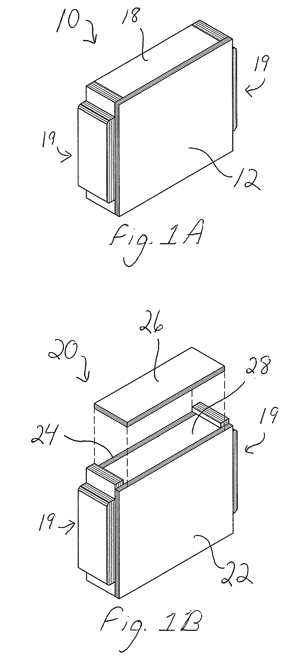
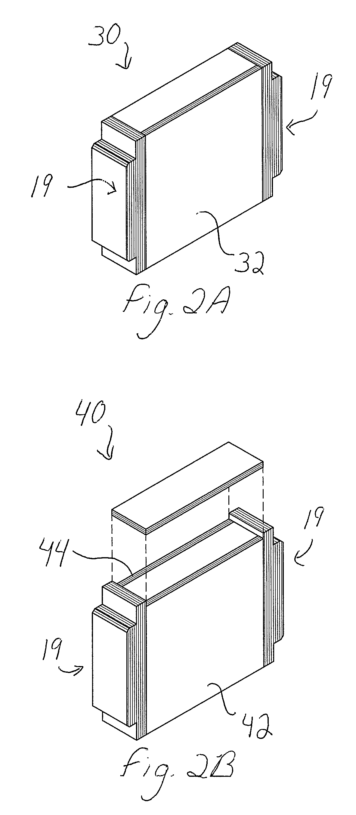
[0043]Referring to the Figures, there are shown several, but not the only, embodiments of the invented Insulated Blocking Panel and Assembly for I-Joist Installation in Floors and Ceilings and Methods for Installing Same. FIGS. 1A, 1B, 2A, 2B, 3, 4, 5A, and 5B illustrate some, but not the only, embodiments of the insulated blocking panels. The inventors believe these and other embodiments of the invented insulated blocking panels will be beneficial in many I-joist installations using conventional I-joists and conventional rim boards, and, also, in I-joist installations using their earlier-invented apparatus, including their invented rim boards and / or their invented, precision-machined support blocks.

[0044]Regarding embodiments such as those shown in FIGS. 1A, 1B, 2A, 2B, 5A, and 5B, for example, the support blocks are secured and immovably fixed to the foam board and / or the vertical structural panels, prior to installation and preferably at the time of manufacture. Such support bloc...


PUM


Abstract

Apparatus and methods for spacing, securing, and stabilizing I-joists at their ends, and insulating and structural enhancing I-joist assemblies, are provided around the perimeter, or in the interior, of a floor or ceiling where ends of I-joists are located. Insulated blocking panels may comprise an insulating portion that provides a high-R-value and a structural portion which may comprise vertical panel(s) and optional integral support blocks that provide a profiled end surface for extending to the web of the I-joists. Alternatively, insulated blocking panels with flat, vertical end surfaces may be used with field-installed support blocks, or insulated blocking panels with profiled end surfaces may be used without any support blocks. The support blocks or profiled end surfaces of the insulated blocking panels extend to the web of each I-joist, to fill in the space between the I-joists near the I-joist ends, including a substantial amount of the space immediately adjacent the web of each I-joist. The preferred insulated blocking panels, therefore, insulated the outer perimeter of a floor or ceiling and also contribute vertical load carrying capability, and lateral shear and roll-over resistance.

Description

DESCRIPTION[0001]This application claims priority of Provisional Application 60 / 916,288, filed May 5, 2007, and this application is a continuation-in-part of U.S. Non-Provisional application Ser. No. 11 / 148,125, filed Jun. 7, 2005 now abandoned , which is a continuation of U.S. Non-Provisional application Ser. No. 10 / 376,556, filed Feb. 27, 2003 and issued on Jun. 7, 2005 as U.S. Pat. No. 6,901,715, which claims priority of Provisional Application, 60 / 360,763, filed Feb. 27, 2002, the entire disclosures of which are hereby incorporated by this reference.BACKGROUND OF THE INVENTION[0002]1. Field of the Invention[0003]The invention relates to improved apparatus and methods for construction of floor joist and ceiling joist systems. More specifically, the invention relates to improved apparatus that may be installed at the ends of I-joists around the perimeter of a floor or ceiling, or at other locations where I-joist ends are secured into the floor or ceiling structure. The invention m...

Claims


Application Information

Patent Timeline
Patent Type & Authority Patents(United States)
IPC IPC(8): E04C3/00
CPCE04B5/12E04B1/2612E04C2003/026
Inventor BROWN, LAWRENCEBROWN, COMER
Owner SILPRO
Why Eureka
Try Eureka