Clutch-manipulation assist mechanism

a technology of assist mechanism and clutch, which is applied in the direction of clutches, fluid actuated clutches, non-mechanical actuated clutches, etc., can solve the problems of inability to obtain smooth assisting force, and achieve the effect of enhancing the vibration resistance and wear resistance of the detection portion, reducing the width of the transmission, and reducing the difficulty of operation

Inactive Publication Date: 2010-11-09
HONDA MOTOR CO LTD
View PDF14 Cites 8 Cited by
  • Summary
  • Abstract
  • Description
  • Claims
  • Application Information

AI Technical Summary

Benefits of technology

[0014]To explain the manner of operation, the push rod member is movable in the axial direction interlockingly with the power cutoff of the clutch mechanism due to the manipulation of the clutch manipulation member by the rider. Accordingly, by operating the actuator when the detection means detects the movement quantity of the shaft end of the push rod member, the movement of the push rod member in the axial direction is assisted and hence, a manipulation force of the rider for manipulating the clutch manipulation member can be decreased.
[0020]To explain the manner of operation, for example, when the detection portion of the detection means is directly and perpendicularly brought into contact with the shaft end of the push rod member, the detection portion of the detection means always receives a force from the push rod member in the direction perpendicular to the stroke direction of the detection portion. Accordingly, when the clutch-manipulation assist mechanism is used for a long time in such a state, there may be a case that the detection portion may be mounted with a play or is worn. Accordingly, by providing the intermediate member between the shaft end of the push rod member and the detection portion of the detection means and by bringing the intermediate member into contact with the shaft end of the push rod member, the vibration resistance and the wear resistance of the detection portion of the detection means can be enhanced.
[0024]According to the first aspect of the present invention, the detection portion of the detection means detects the movement quantity of the shaft end of the push rod member and hence, it is possible to always make the timing of sensing by the detection means and the timing of power cutoff by the clutch mechanism agree with each other thus allowing the clutch-manipulation assist mechanism to respond to the power cutoff by the clutch mechanism with the favorable responsiveness.
[0025]According to the second aspect of the present invention, the detection portion is arranged to be movable in the direction perpendicular to the movement of the push rod member and hence, it is possible to suppress the projection quantity of the detection means in the axial direction of the push rod member while arranging the detection means on the shaft end of the push rod member. Accordingly, for example, a width of the transmission to which the push rod member and the detection means are provided can be decreased.
[0026]According to the third aspect of the present invention, the intermediate member which is movable in the stroke direction of the detection portion is provided between the shaft end of the push rod member and the detection portion of the detection means and hence, a force in the direction perpendicular to the axial direction is not directly applied to the detection portion of the detection means thus enhancing the vibration resistance and the wear resistance of the detection portion of the detection means.
[0027]According to the fourth aspect of the present invention, the assist input portion being operable by the actuator is arranged in the vicinity of the shaft end of the push rod member on which the detection means is mounted, and the input portion for inputting the manipulation force from the clutch manipulation member to the push rod member is mounted on the shaft end on the side opposite to the shaft end. Accordingly, it is possible to prevent the input portion for inputting the manipulation force from the clutch manipulation member to the push rod member, the detection portion of the detection means and the assist input portion from being arranged on one shaft end of the push rod member in a concentrated manner.

Problems solved by technology

When such timing difference arises, there may be a case that a smooth assisting force can not be obtained.

Method used


Image

  • Clutch-manipulation assist mechanism
  • Clutch-manipulation assist mechanism
  • Clutch-manipulation assist mechanism

Examples


Embodiment Construction

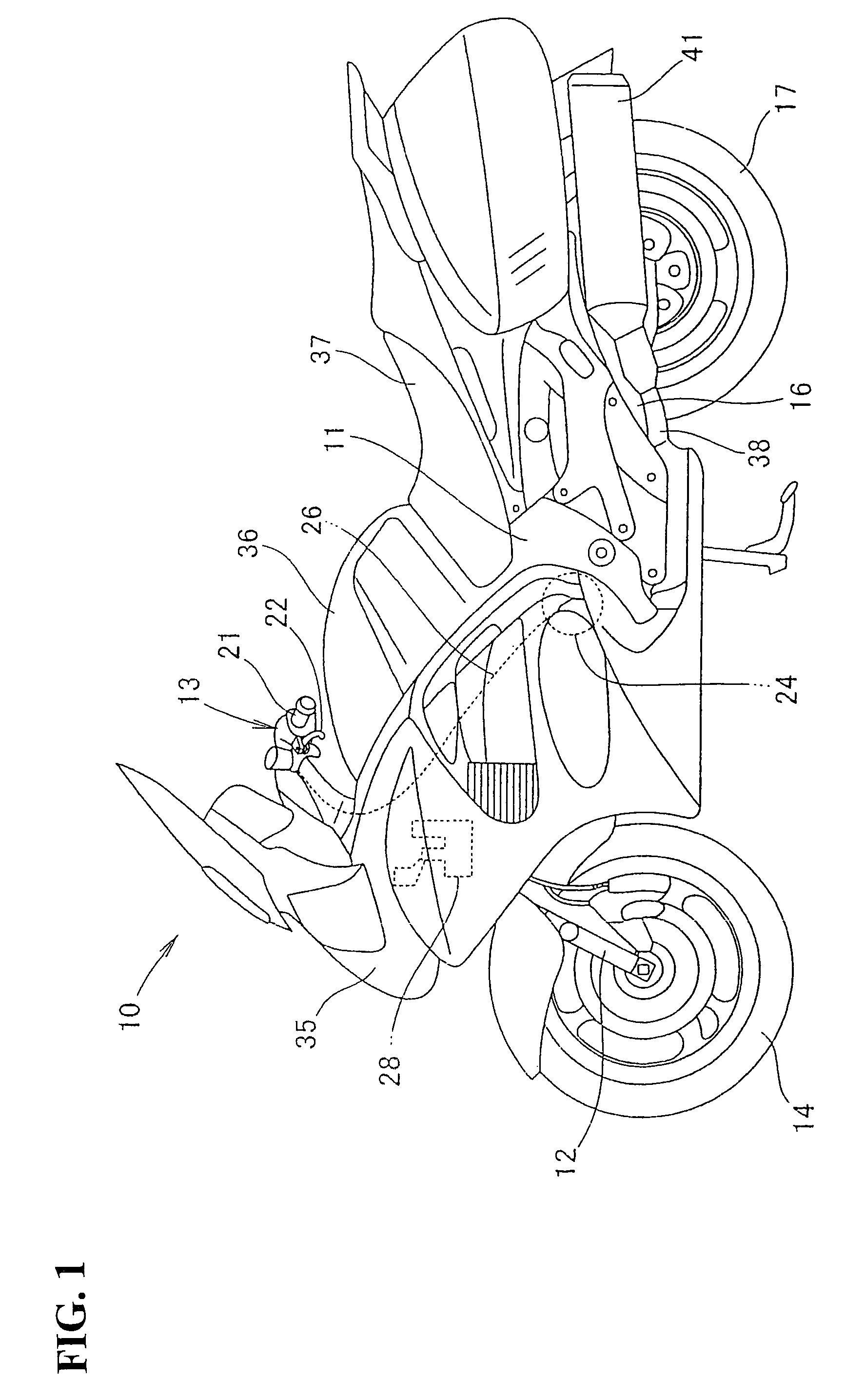
[0036]FIG. 1 is a side view showing a vehicle which includes a clutch-manipulation assist mechanism according to the present invention. In the drawing, the vehicle 10 includes a main frame 11 which constitutes a skeleton of the vehicle 10, a front fork 12 which is steerably mounted on a front end of the main frame 11, a bar handle 13 and a front wheel 14 which are respectively mounted on an upper end and a lower end of the front fork 12, a power unit (not shown in the drawing) which is mounted on a lower portion of the main frame 11, a swing arm 16 which is swingably mounted on a rear lower portion of the main frame 11, and a rear wheel 17 which is mounted on a rear end of the swing arm 16 and is driven by the power unit.

[0037]A left grip 21 and a clutch lever 22 are mounted on a left side of the bar handle 13.

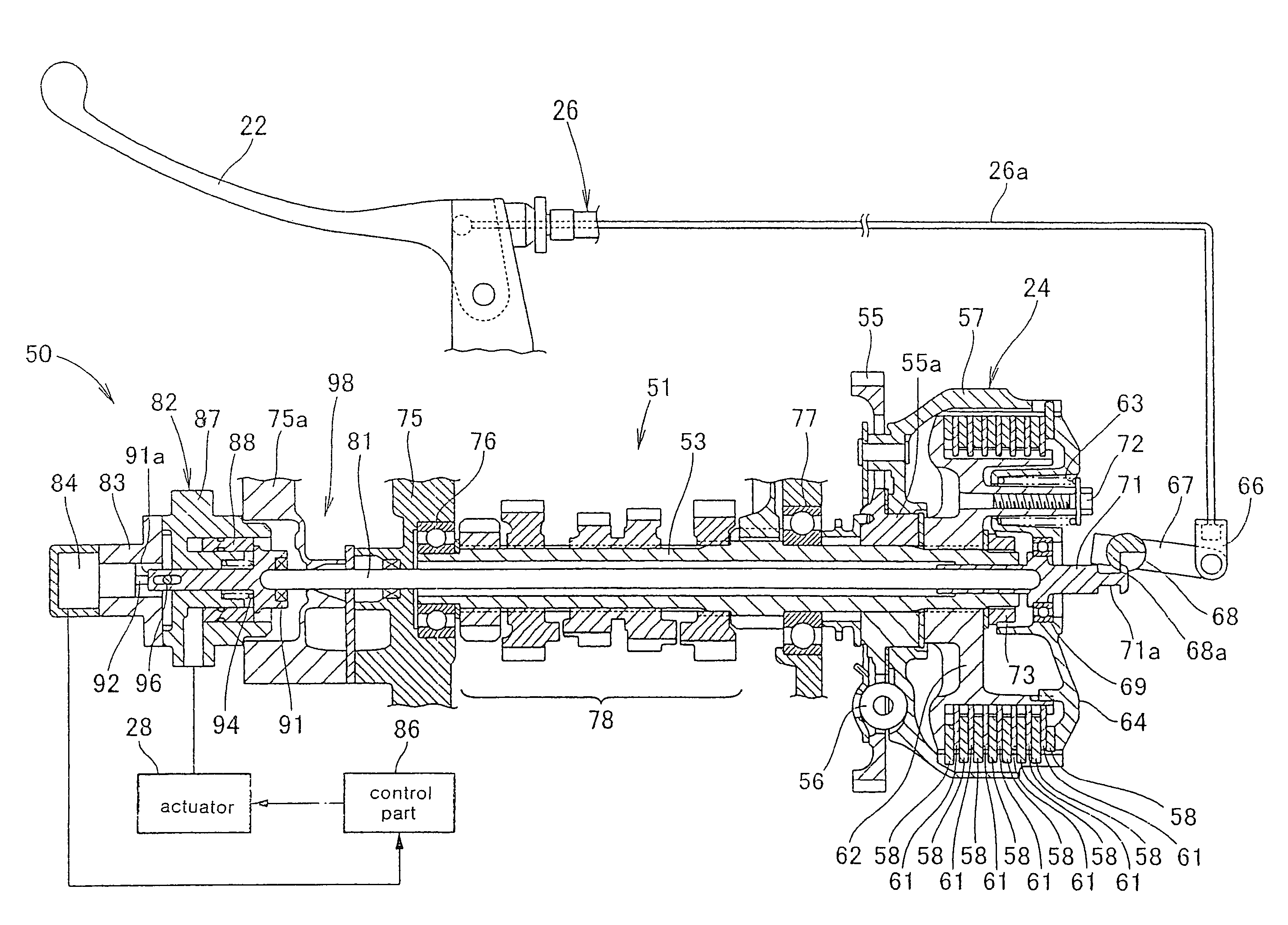
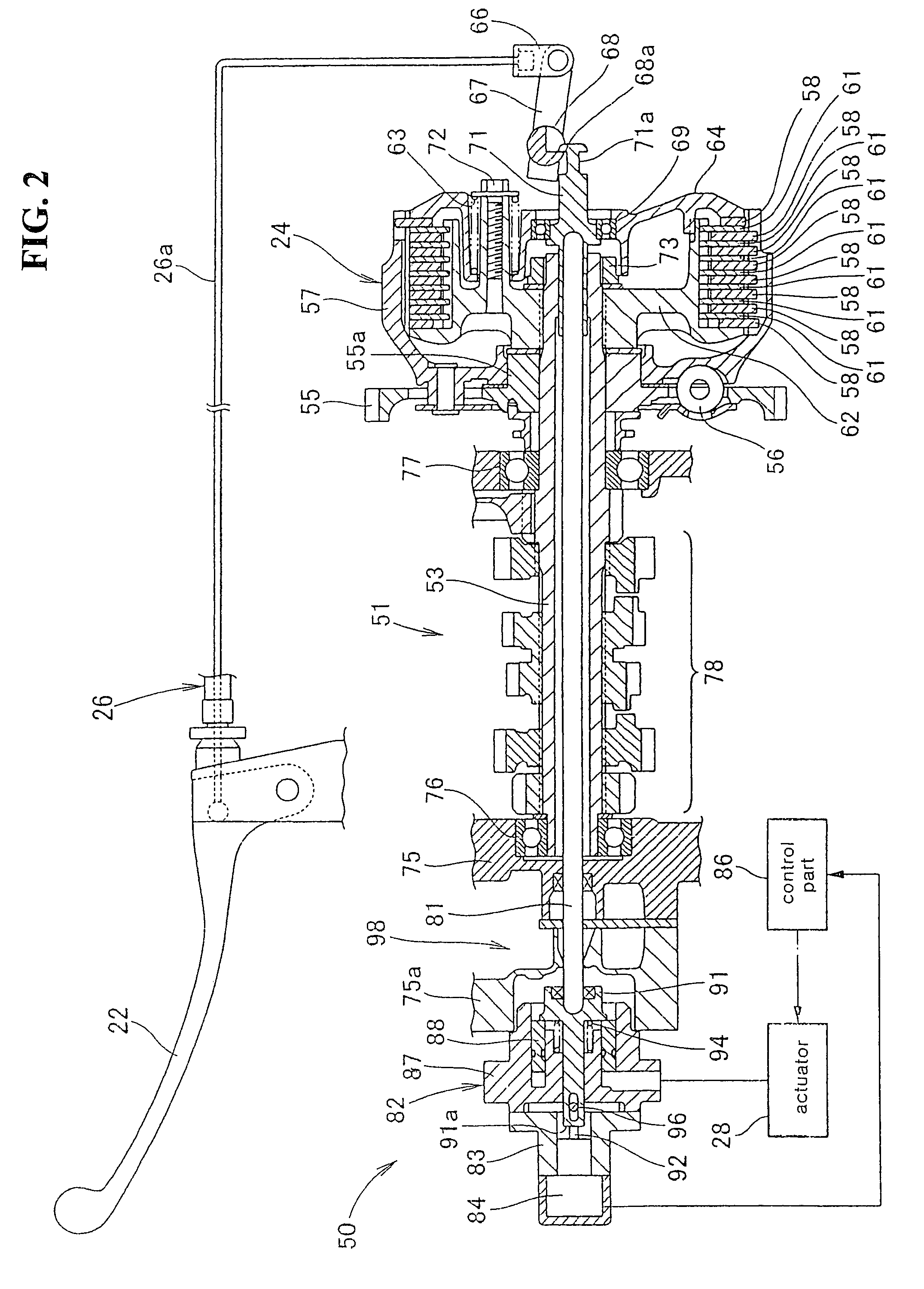
[0038]The power unit is constituted of an engine and a transmission, and a clutch mechanism 24 is mounted on a side portion of the transmission.

[0039]The clutch mechanism 24 i...


PUM


Abstract

A clutch-manipulation assist mechanism of a vehicle clutch mechanism is capable of disconnecting power of an engine and is provided to a power transmission path which transmits the power of the engine to a rear wheel. The clutch-manipulation assist mechanism includes a push rod member which is arranged near the clutch mechanism and which is movable in the axial direction interlockingly with a power cutoff of the clutch mechanism due to the manipulation of a clutch lever by a rider. An axial movement of the push rod member is assisted by an actuator in response to a detection of the clutch lever manipulation by the rider using a stroke sensor, thus reducing a manipulation force of the clutch lever. A detection lug of the stroke sensor detects a movement quantity of a shaft end of the push rod member.

Description

CROSS-REFERENCE TO RELATED APPLICATION[0001]The present application claims priority under 35 U.S.C. §119 to Japanese Patent Application No. 2006-265299, filed Sep. 28, 2006, the entire contents of which are hereby incorporated by reference.BACKGROUND OF THE INVENTION[0002]1. Field of the Invention[0003]The present invention relates to an improvement of a clutch-manipulation assist mechanism.[0004]2. Description of Background Art[0005]As a conventional clutch-manipulation assist mechanism, there has been known a clutch-manipulation assist mechanism which extends a wire cable from a clutch lever to a clutch mechanism of an engine, and mounts a sensor which detects the manipulation of the clutch lever on an intermediate portion of the wire cable.[0006]Hereinafter, the above-mentioned clutch-manipulation assist mechanism shown in FIG. 1 to FIG. 3 of JP-A-2005-67450 is explained.[0007]A clutch lever 12 is mounted on a handle of a motorcycle, a clutch mechanism is mounted on an engine 11 ...

Claims


Application Information

Patent Timeline
Patent Type & Authority Patents(United States)
IPC IPC(8): F16D25/08F16D23/12
CPCF16D25/086F16D48/04Y10T477/79F16D2500/1117F16D2500/3026F16D2500/70406F16D2500/7041F16D2300/24
Inventor IWASHITA, KANAUNIWANO, ATSUKO
Owner HONDA MOTOR CO LTD
Why Eureka
Try Eureka