Fuel cell production method and fuel cell

a fuel cell and production method technology, applied in the direction of cell components, final product manufacturing, sustainable manufacturing/processing, etc., can solve the problems of complicated production process, achieve sufficient porosity, convenient and convenient electrode production, and sufficient current collection characteristics

Inactive Publication Date: 2010-11-09
TOYOTA JIDOSHA KK
View PDF20 Cites 0 Cited by
  • Summary
  • Abstract
  • Description
  • Claims
  • Application Information

AI Technical Summary

Benefits of technology

[0007]It is an object of the invention to easily and conveniently produce an electrode that has both a sufficient porosity and a sufficient current collection characteristic.
[0009]According to the production method for the fuel cell of the invention constructed as in the above, a dense layer is formed on the electrolyte layer, and the initial electrochemical reaction is carried out in the fuel cell structure that includes the electrolyte layer and the dense layer, whereby a fuel cell having porous electrodes can be completed. Therefore, a fuel cell provided with porous electrodes can be very easily and conveniently produced. Since the electrode is formed by causing formation of many micropores in the dense layer, it is possible to sufficiently secure electrical continuity in the entire electrode formed, and enhance the current collection characteristic of the electrode.
[0011]If the film thickness of the dense layer is 10 nm or greater as in the foregoing, it becomes possible to secure a denseness of the dense layer made of a solid oxide, and enhance the current collection characteristic of the electrode formed from the dense layer. Furthermore, if the film thickness of the dense layer is 200 nm or less as in the foregoing, it is possible to enhance the efficiency of formation of micropores in the dense layer caused by the water created between the electrolyte and the dense layer in step (d), and thus obtain an electrode that has sufficiently many micropores.
[0015]In the case where the electrolyte layer is formed of a solid oxide that has a flat surface, it generally becomes difficult to secure many portions of contact between the electrolyte layer and the electrode when a porous electrode is formed on the electrolyte layer. Therefore, by forming the dense layer by the film forming method in which the electrode material is closely adhered to the electrolyte layer at the atomic level, it becomes possible to more remarkably obtain the effect of increasing the portions of contact (three-phase interfaces) between the electrolyte layer and the electrode.
[0017]In this case, since the electrolyte layer is formed as a film on the metal layer that has hydrogen permeability, the electrolyte layer can be reduced in thickness. Therefore, it is possible to obtain, through an easy and convenient production process, a fuel cell that is a solid electrolyte fuel cell whose operation temperature is lower, and that is provided with a cathode electrode that has an excellent porosity and an excellent current collection characteristic.
[0019]According to the production method for the electrolyte-electrode conjugate of the invention constructed as in the above, a dense layer is formed on the electrolyte layer, and the initial electrochemical reaction is carried out in the structure that includes the electrolyte layer and the dense layer, whereby an electrolyte-electrode conjugate having a porous electrode can be completed. Therefore, fuel cell-purpose electrodes that are porous can be very easily and conveniently produced. Since the electrode is formed by causing formation of many micropores in the dense layer, it is possible to sufficiently secure electrical continuity in the entire electrode formed, and enhance the current collection characteristic of the electrode.

Problems solved by technology

However, the production method for the electrode requires a process of heating and, furthermore, a process of joining the obtained mesh-like thin film electrode onto an electrolyte layer, resulting in a complicated production process.

Method used


Image

  • Fuel cell production method and fuel cell
  • Fuel cell production method and fuel cell
  • Fuel cell production method and fuel cell

Examples


examples

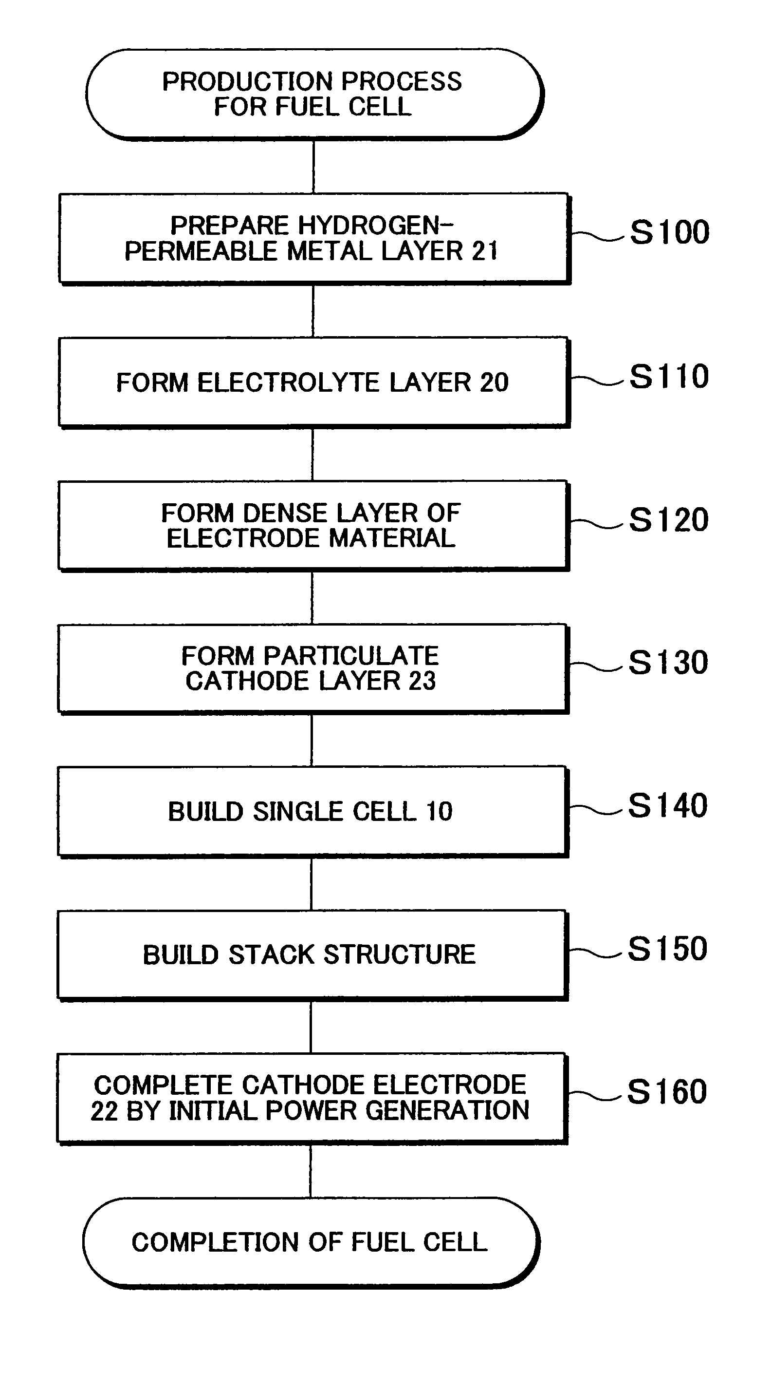
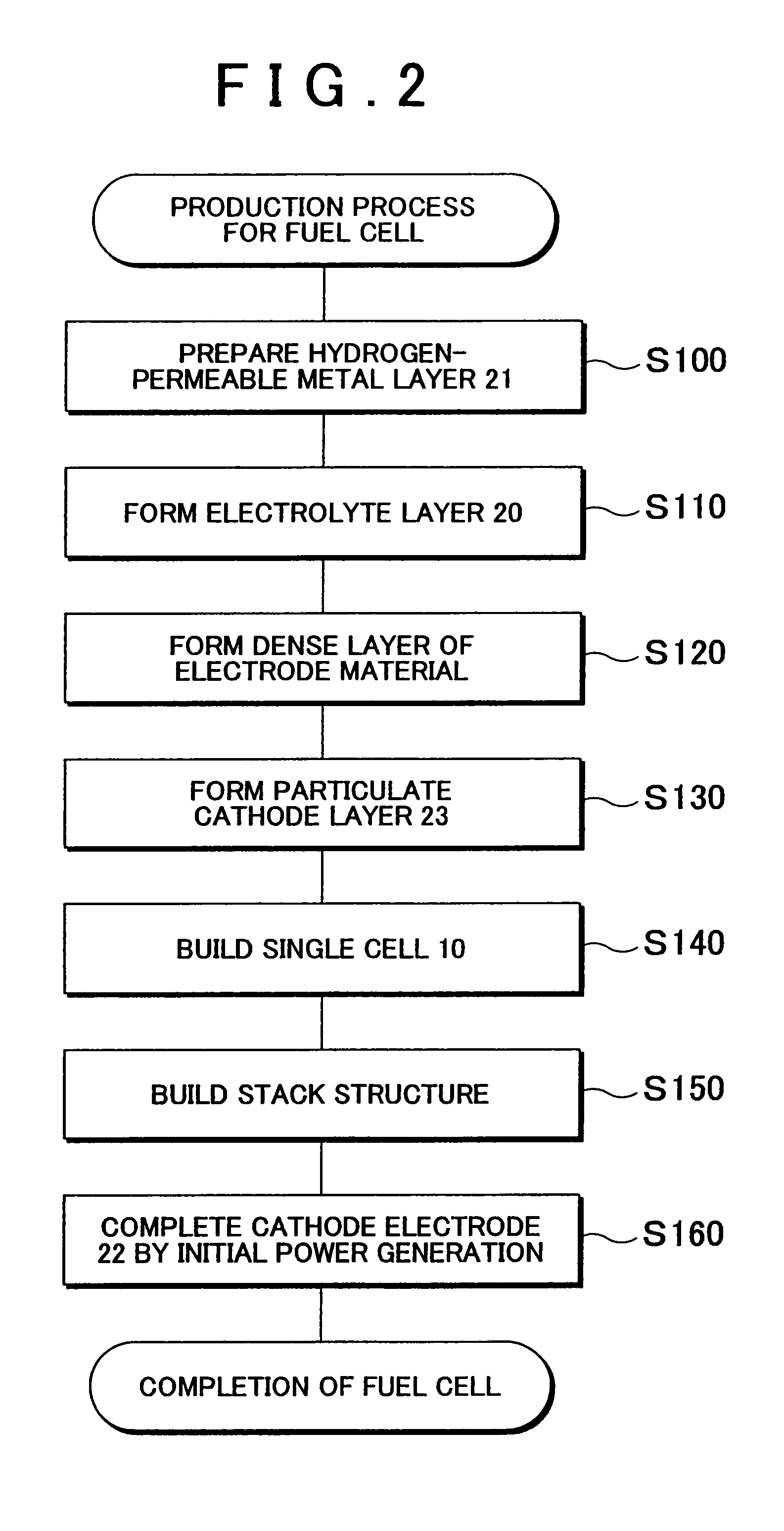
[0076]Fuel cells of the first and second samples of the invention, and a fuel cell of a first comparative example were produced, and their cathode electrodes were compared in appearance.

(A) Production of Fuel Cell

(A-1) First Sample

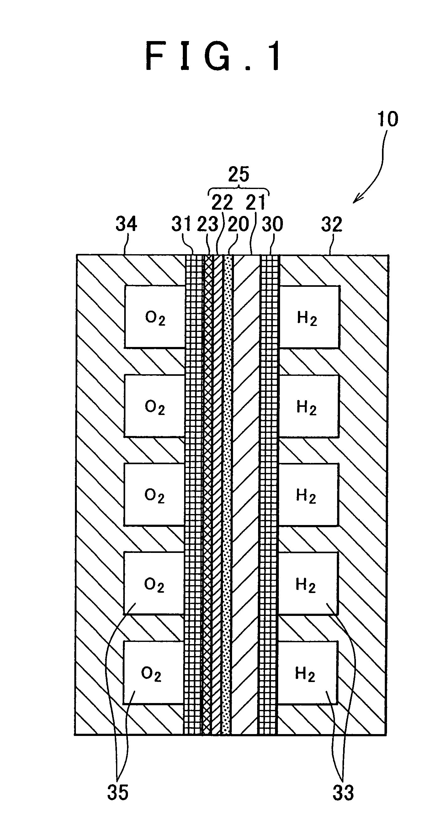
[0077]The fuel cell of the first sample has a construction similar to that shown in FIG. 1. In the fuel cell of the first sample, a Pd substrate of 80 μm in thickness was used as a hydrogen-permeable metal layer 21. Furthermore, the electrolyte layer 20 was fabricated by forming a layer of BaCe0.8Y0.2O3 of 2 μm in thickness as a film on the hydrogen-permeable metal layer 21 through the PLD method. The dense layer 22a for forming the cathode electrode 22 was fabricated by forming a layer of La0.6Sr0.4CoO3 of 25 nm in thickness as a film on the electrolyte layer 20 through the PLD method. The particulate cathode layer 23 was formed by screen printing through the use of a paste containing fine particles of 0.9 μm in average particle diameter made of the same ...


PUM

PropertyMeasurementUnit
thicknessaaaaaaaaaa
thicknessaaaaaaaaaa
thicknessaaaaaaaaaa

Abstract

First, a solid-state electrolyte layer that has conductivity for ions of one of hydrogen and oxygen is formed. After that, a dense layer made of an electrode material that has electron conductivity, catalyst activity to accelerate the electrochemical reaction, and a characteristic of allowing permeation of ions and / or atoms of the other one of hydrogen and oxygen is formed on a surface of the electrolyte layer. Then, a fuel cell structure that includes the electrolyte layer and the dense layer is built. After that, the electrochemical reaction is caused to progress by supplying a fuel and oxygen to the fuel cell structure, so that in the dense layer, many micropores extending through the dense layer in the film thickness direction are created due to the generated water that is created between the electrolyte layer and the dense layer.

Description

BACKGROUND OF THE INVENTION[0001]1. Field of the Invention[0002]This invention relates to a fuel cell production method, and a fuel cell.[0003]2. Description of the Related Art[0004]In order to cause electrochemical reactions to progress in a fuel cell, it is important to sufficiently secure places for the electrochemical reactions, specifically, three-phase interfaces that are interfaces among an electrode (catalyst), an electrolyte layer and a space to which reaction gases containing electrode active materials are supplied, and efficiently supply the reaction gases to the three-phase interfaces. In order to secure the three-phase interface and efficiently supply the reaction gases to the three-phase interfaces, the electrodes have been formed of porous materials that have gas permeability.[0005]Furthermore, in causing the electrochemical reactions to progress in a fuel cell, it is important to secure a current collection characteristic of electrodes. That is, it is important to ca...

Claims


Application Information

Patent Timeline
Patent Type & Authority Patents(United States)
IPC IPC(8): H01M8/10H01M8/24
CPCH01M4/8885H01M4/9016H01M4/94H01M8/1213H01M4/86Y10T29/49115H01M4/9033H01M8/10H01M8/1004H01M8/1253H01M8/126H01M2008/1293Y02E60/521Y02E60/525H01M4/8657Y02E60/50Y02P70/50
Inventor IIJIMA, MASAHIKO
Owner TOYOTA JIDOSHA KK
Why Eureka
Try Eureka