Check patentability & draft patents in minutes with Patsnap Eureka AI!

Method and system for providing a microelectronic device using a plurality of focus distances

a microelectronic device and focus distance technology, applied in the field of providing a microelectronic device using a plurality of focus distances, can solve the problems of adversely affecting the performance of the conventional pmr head, affecting the photolithography process window,

Inactive Publication Date: 2010-11-09
WESTERN DIGITAL TECH INC
View PDF9 Cites 148 Cited by
  • Summary
  • Abstract
  • Description
  • Claims
  • Application Information

AI Technical Summary

Benefits of technology

[0008]FIG. 1 is a flow chart depicting a conventional method for providing a conventional PMR head.
[0009]FIGS. 2-4 depict a conventional perpendicular magnetic recording head during fabrication.
[0010]

Problems solved by technology

Other methods for controlling the angle θ may adversely impact the photolithography process window.
Such a difference may adversely affect performance of the conventional PMR heads 30 and 70.

Method used


Image

  • Method and system for providing a microelectronic device using a plurality of focus distances
  • Method and system for providing a microelectronic device using a plurality of focus distances
  • Method and system for providing a microelectronic device using a plurality of focus distances

Examples


Embodiment Construction

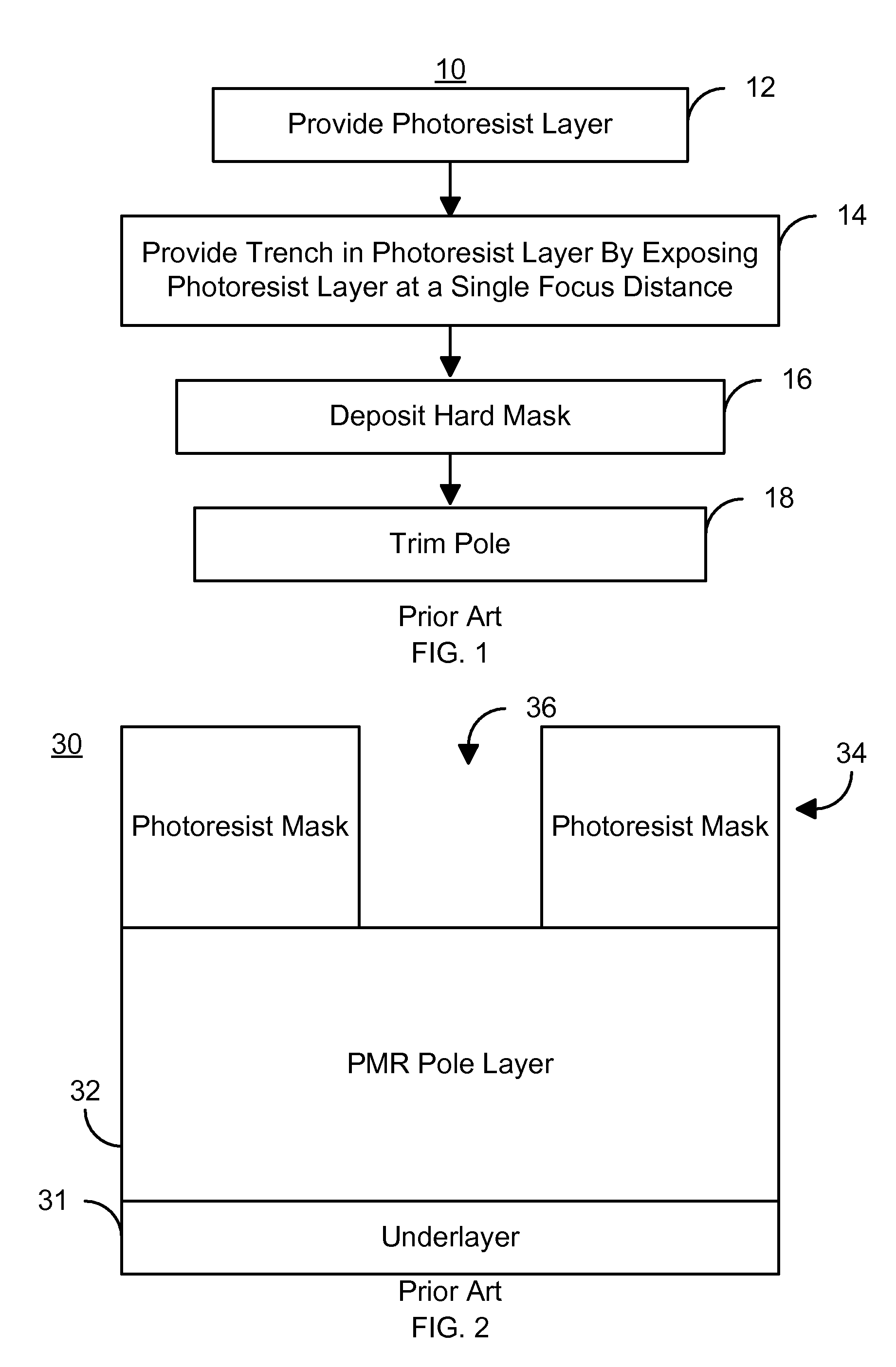
[0019]FIG. 9 is a flow chart depicting an exemplary embodiment of a method 100 for fabricating a structure in a microelectric device, such as a PMR head. For simplicity, some steps in the method 100 may be omitted. Consequently, other and / or additional steps not inconsistent with the method and system may be used. The method 100 is described in the context of and preferably used for providing a PMR pole of a PMR head. However, in another embodiment, the method 100 may be used in providing another structure that may be in another type of head and / or another type of microelectric device. For example, the method 100 may be used in providing a conductive line. FIGS. 10A-10C depict an exemplary embodiment of the set-up 110 for a microelectric device 114 undergoing exposure of photoresist at a plurality of focus distances using the method 100. For simplicity, the system 110 and its components are not to scale.

[0020]Referring to FIGS. 9 and 10A-10C, a photoresist layer is provided on the m...


PUM


Abstract

A method and system for providing a microelectric device are described. The method and system include providing a photoresist layer having a surface. The method and system also include setting a focus range and exposing the photoresist layer over the focus range to form a photoresist mask having a trench therein. The focus range corresponding to a plurality of focus distances. The focus range also corresponds to a nonzero angle to be formed in the photoresist layer and to the structure. The trench has at least one sidewall that forms the angle with a normal to the surface. The method and system also include providing the structure utilizing the trench.

Description

BACKGROUND[0001]FIG. 1 depicts a conventional method 10 for fabricating a conventional perpendicular magnetic recording (PMR) pole of a conventional PMR transducer. FIGS. 2-4 depict the conventional PMR head 30 during fabrication using the conventional method 10 as viewed from the air-bearing surface (ABS). For clarity, the conventional PMR head 30 is not to scale. Referring to FIGS. 1-4, the method 10 commences after formation of an alumina underlayer. The conventional method 30 starts after the PMR pole layer has been deposited. Thus, the magnetic material(s) to be used for the PMR pole have been deposited on the conventional PMR head 30. A photoresist layer is provided, via step 12. The photoresist layer is exposed using a single focus distance, otherwise known as a fixed focus offset, for the entire exposure, via step 14. In step 14, the wafer on which the conventional PMR head 30 is formed and reticle (not shown) used are not moved with respect to each other during the exposure...

Claims


Application Information

Patent Timeline
IPC IPC(8): G03F7/20
CPCG03F7/70333G11B5/1278G11B5/1871G11B5/3116G11B5/3163
Inventor WANG, YIZHONGSUN, HAIYUAN, HONGPINGYU, WINNIE
Owner WESTERN DIGITAL TECH INC
Features
  • R&D
  • Intellectual Property
  • Life Sciences
  • Materials
  • Tech Scout
  • Unparalleled Data Quality
  • Higher Quality Content
  • 60% Fewer Hallucinations
Learn More