Underground utility locator with a transmitter, a pair of upwardly opening pockets and helical coil type electrical cords

a technology of underground utility locators and transmitters, which is applied in the direction of electric/magnetic detection for transportation, using reradiation, instruments, etc., can solve the problems of affecting the comfort and convenience of residents, and affecting the use of the utility locator. the effect of convenien

Inactive Publication Date: 2010-11-09
SEEKTECH
View PDF17 Cites 61 Cited by
  • Summary
  • Abstract
  • Description
  • Claims
  • Application Information

AI Technical Summary

Benefits of technology

[0010]It is therefore the primary object of the present invention to provide a portable sonde and line locator that is easier to use.

Problems solved by technology

If a back hoe or other excavation equipment hits a high voltage line or a gas line, serious injury and property damage can result.
Severing water mains and sewer lines leads to messy cleanups.
The destruction of power and data cables can seriously disrupt the comfort and convenience of residents and cost businesses huge financial losses.
A typical low frequency sonde does not strongly couple to other objects and thereby produce complex interfering fields that can occur during tracing.
Those that have been commercialized have been difficult to use primarily because they are extremely sensitive to the orientation of their antennas relative to the buried object.
This can confuse the operator, especially if he or she interprets a smaller peak as the buried object.
Conventional battery powered portable sonde and line locators have also suffered from user interfaces that are cumbersome to use, inflexible and / or limited in their ability to convey useful information.
They typically have a small array of labeled push buttons and a display that is primarily dedicated to indicating numerical values in a manner that is not easy for the operator to interpret.
Conventional transmitters are commercially available that will output several different signals at different frequencies that can be applied to the same underground object or even to different underground objects, but the line locators that have heretofore been commercially available have not been capable of simultaneously detecting and indicating the locations of the different objects, their depths or their different types.

Method used


Image

  • Underground utility locator with a transmitter, a pair of upwardly opening pockets and helical coil type electrical cords
  • Underground utility locator with a transmitter, a pair of upwardly opening pockets and helical coil type electrical cords
  • Underground utility locator with a transmitter, a pair of upwardly opening pockets and helical coil type electrical cords

Examples


first embodiment

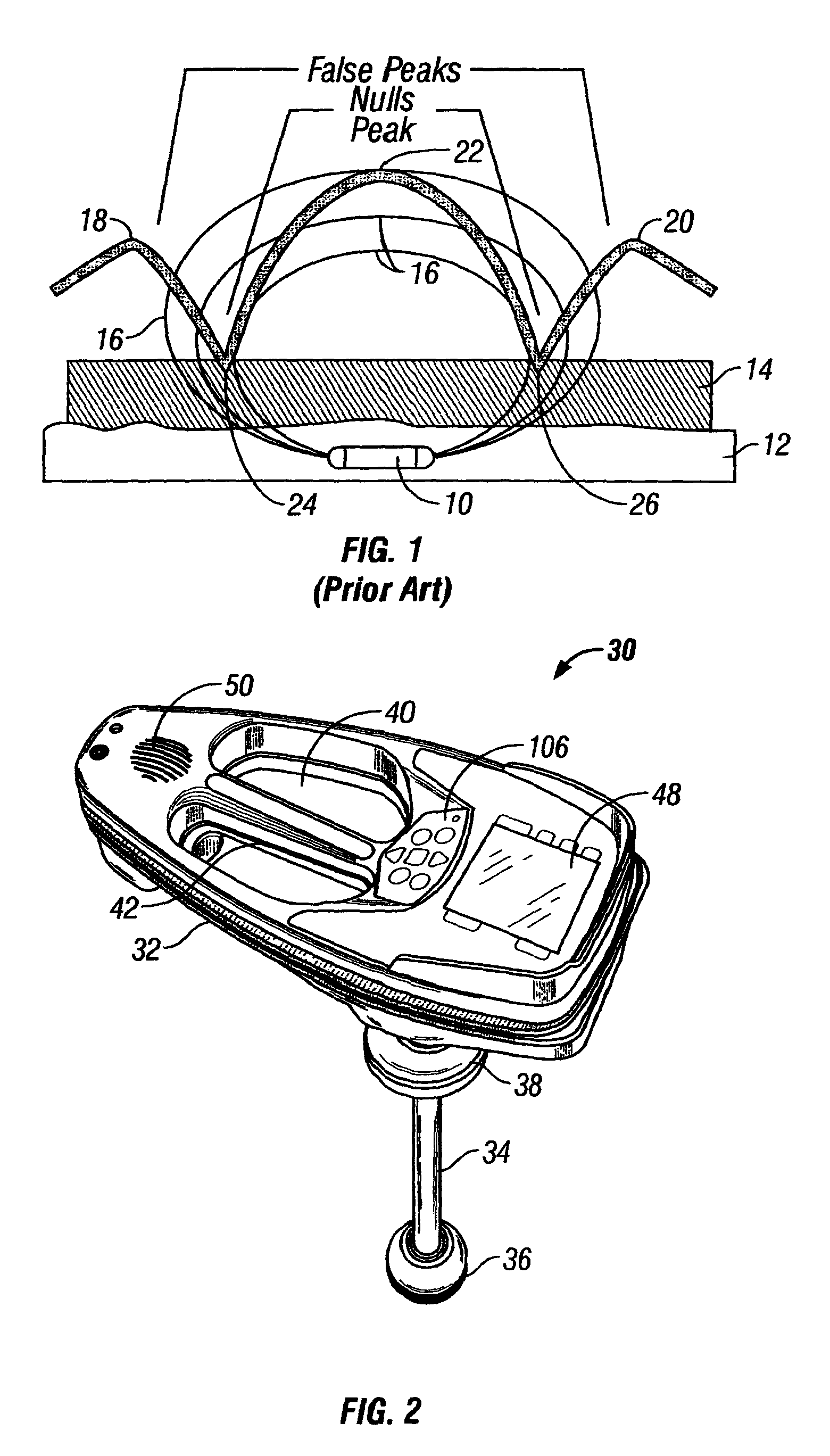
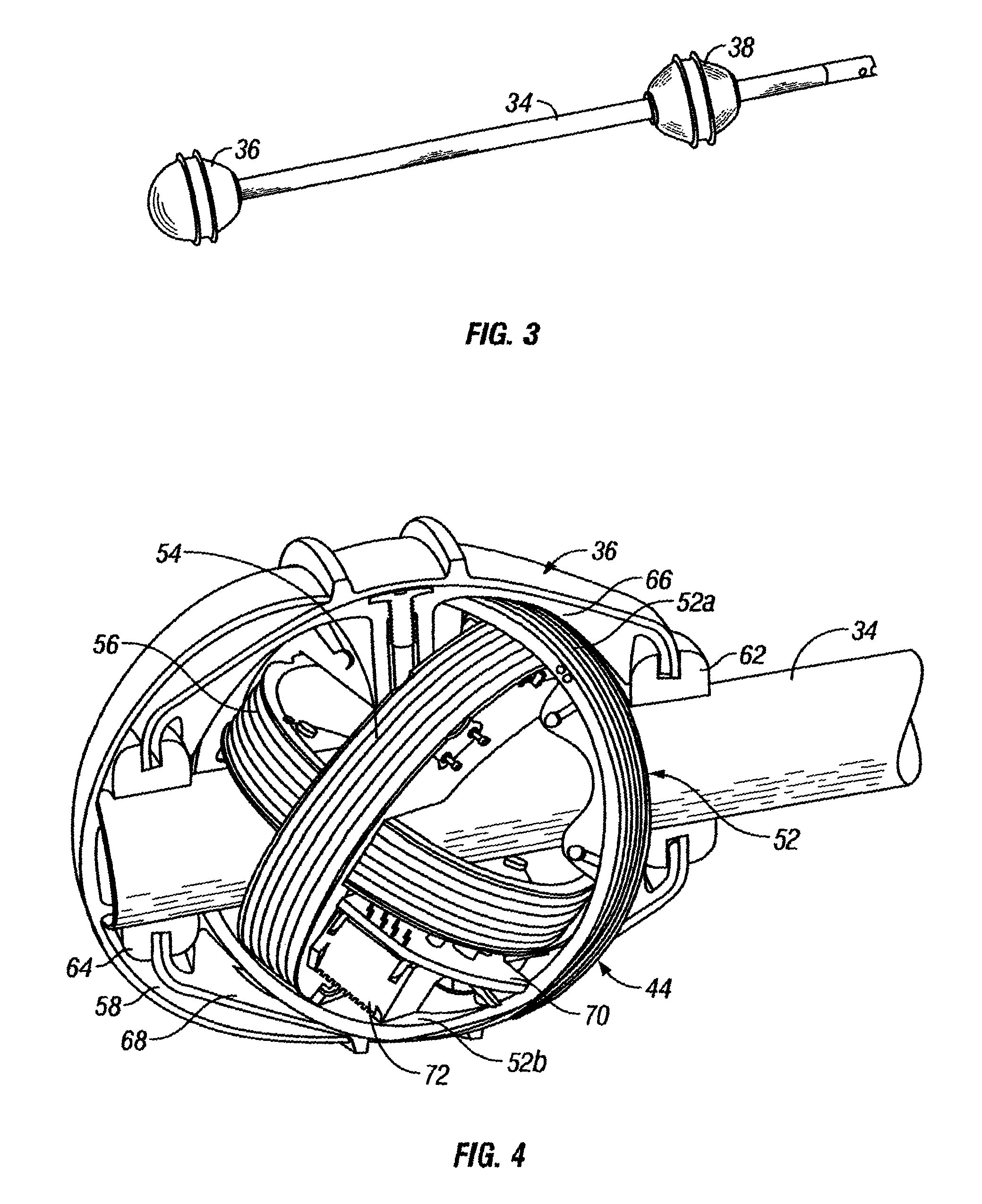
[0054]Referring to FIG. 2, the present invention is illustrated in the form of a battery powered, omnidirectional, manually portable system 30 that is capable of locating a buried object by sensing an electromagnetic signal emitted by the buried object. The system 30 includes a housing 32 and an elongate member 34 (FIG. 3) that supports spaced apart lower and upper sensor balls 36 and 38, respectively, and connects them to the housing 32. The housing 32 (FIG. 2) is made of openable rigid plastic shells having a large central aperture 40 spanned by a handle portion 42.

[0055]Circuit means illustrated in FIG. 6 are mounted partly in the housing 32 and partly in the sensor balls 36 and 38 for sensing an electromagnetic signal in a frequency range of approximately 50 Hz to 500 kHz emitted from a buried object and determining a location and depth of the buried object by measuring signal strength and field angles in three dimensions. This is accomplished utilizing a first lower antenna arr...

second embodiment

[0097]FIG. 18 is an enlarged top plan view of a portion of the housing 32 of the second embodiment illustrating its display 48 and keypad 106 and showing an exemplary trace mode MAP view in which the locations of a plurality of different underground utilities are simultaneously visually indicated. A phone utility icon 228 is indicated on the display 48 without the line orientation feature selected. An electric utility icon 230 is indicated on the display 48 with the line orientation feature selected and indicated by a solid bold diagonal line 232. A 60 Hz icon 234 is indicated on the display 48 without the line orientation feature selected. A gas utility icon 236 is indicated on the display 48 without the line orientation feature selected.

[0098]Continuing with FIG. 18, if a sonde is being used, the sonde frequency and level are indicated at a location 238 in the upper left corner of the display 48. No values for the sonde frequency and level are illustrated in FIG. 18. High, medium ...


PUM


Abstract

A transmitter for use with an underground utilities locator including a portable elongate housing; an electronic circuit mounted in the housing and configured to generate an electrical output signal at a frequency suitable for tracing an underground utility; a pair of springy helical coil type electrical cords each having an inner end connected to the circuit; means electrically connected to an outer end of each of the electrical cords for coupling the predetermined electrical output signal across the underground utility; and the housing having a pair of upwardly opening pockets formed on opposite ends of the elongate housing and each sized to permit the electrical cords to be wrapped into loops and stowed into corresponding ones of the pockets.

Description

CROSS REFERENCE TO RELATED APPLICATION[0001]This application is a division of currently U.S. patent application Ser. No. 11 / 077,947, filed Mar. 11, 2005, which itself is a division of U.S. Ser. No. 10 / 308,752 filed Dec. 3, 2002 (now abandoned), as well as a continuation-in-part of U.S. Ser. No. 10 / 268,641 filed Oct. 9, 2002, now U.S. Pat. No. 7,009,399 granted Mar. 7, 2006. The entire disclosures of each of the aforementioned patent applications are hereby incorporated in their entirety by reference.FIELD OF THE INVENTION[0002]The present invention relates to electronic systems and methods for locating buried or otherwise inaccessible pipes and other conduits, as well as cables, conductors and inserted transmitters, by detecting an electromagnetic signal emitted by these buried objects.BACKGROUND OF THE INVENTION[0003]There are many situations where is it desirable to locate buried utilities such as pipes and cables. For example, prior to starting any new construction that involves ...

Claims


Application Information

Patent Timeline
Patent Type & Authority Patents(United States)
IPC IPC(8): G01V3/10G01S7/03G01S13/88G01V3/15
CPCG01S7/03G01S13/88G01V3/15G06F3/016G06F3/0346G01S13/885G01V3/08
Inventor OLSSON, MARK S.SHAFFER, DAWN E.
Owner SEEKTECH
Why Eureka
Try Eureka