Architectures for parallelized intersection testing and shading for ray-tracing rendering

a parallelized intersection and rendering technology, applied in the field of rendering two-dimensional representations from three-dimensional scenes, can solve the problems of computational complexity, large time consumption of workstations, and high computational complexity of testing 1024768 (for example) rays for intersections with millions of triangles

Active Publication Date: 2010-11-09
IMAGINATION TECH LTD
View PDF30 Cites 56 Cited by
  • Summary
  • Abstract
  • Description
  • Claims
  • Application Information

AI Technical Summary

Problems solved by technology

However, ray tracing is also known to be computationally intensive, and at present, even a state of the art graphics workstation requires a substantial amount of time to render a complicated scene using ray tracing.
As can be readily understood, the computational complexity of testing 1024×768 (for example) rays for intersection with millions of triangles is computationally expensive- and such ray numbers do not even account for all of the additional rays spawned as a result of material interaction with intersecting rays).
Rendering a scene with ray tracing has been termed an “embarrassingly parallel problem” because color information accumulated for each pixel of an image being produced can be accumulated independently of the other pixels of an image.
Pharr recognizes that the proposed regular scheduling grid may not perform well if a particular scene has non-uniform complexity, i.e., a higher density of primitives in some portions of the scene.
Such rays can be increasingly difficult to identify as rays are reflected, refracted and / or generated during ray tracing.
However, discussion of any of these references and techniques is not an admission or an implication that any of these references, or subject matter in them is prior art to any subject matter disclosed in this application.

Method used


Image

  • Architectures for parallelized intersection testing and shading for ray-tracing rendering
  • Architectures for parallelized intersection testing and shading for ray-tracing rendering
  • Architectures for parallelized intersection testing and shading for ray-tracing rendering

Examples


Embodiment Construction

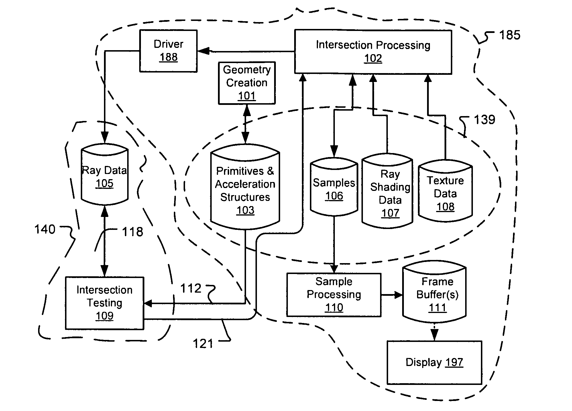
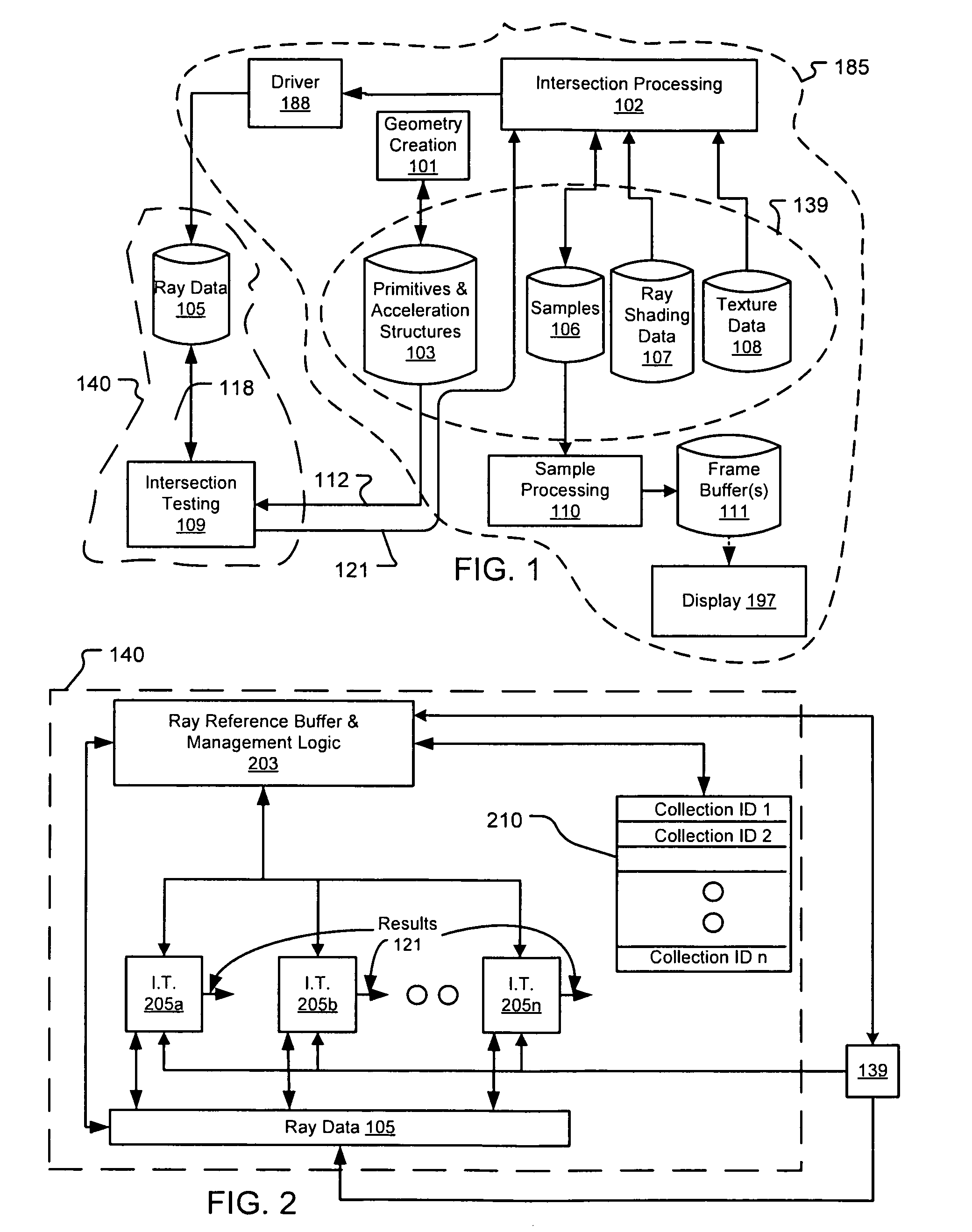
[0060]The following description is presented to enable a person of ordinary skill in the art to make and use various aspects of the inventions. Descriptions of specific techniques, implementations and applications are provided only as examples. Various modifications to the examples described herein may be apparent to those skilled in the art, and the general principles defined herein may be applied to other examples and applications without departing from the scope of the invention. This description first proceeds by introducing aspects relating to an example of a three-dimensional (3-D) scene (FIG. 1), that can be abstracted with geometry acceleration data, as in the example of FIG. 2. Such a 3-D scene can be rendered as a two-dimensional representation with systems and methods according to the examples illustrated and described.

[0061]As introduced in the background, a 3-D scene needs to be converted into a 2-D representation for display. Such conversion requires selecting a camera...


PUM


Abstract

Ray tracing scenes is accomplished using a plurality of intersection testing resources coupled with a plurality of shading resources, communicative in the aggregate through links / queues. A queue from testing to shading comprises respective ray / primitive intersection indications, comprising a ray identifier. A queue from shading to testing comprises identifiers of new rays to be tested, wherein data defining the rays is separately stored in memories distributed among the intersection testing resources. Ray definition data can be retained in distributed memories until rays complete intersection testing, and be selected for testing multiple times based on ray identifier. A structure of acceleration shapes can be used. Packets of ray identifiers and shape data can be passed among the intersection testing resources, and each resource can test rays identified in the packet, and for which definition data is present in its memory. Test results for acceleration shapes are used to collect rays against acceleration shapes, and closest detection ray / primitive intersections are indicated by sending ray identifiers to shading resources.

Description

CROSS REFERENCE TO RELATED APPLICATIONS[0001]This application is a continuation-in-part of U.S. patent application Ser. No. 11 / 856,612, filed on Sep. 17, 2007, which claims priority from and incorporates U.S. provisional application No. 60 / 826,201, entitled “Ray Tracing Enhancements for Graphical Rendering”, filed on Sep. 19, 2006, and claims priority from U.S. provisional application No. 61 / 038,731, entitled “Coupling Ray Storage and Compute for Memory-Efficient Ray Intersection Test Scaling”, filed on Mar. 21, 2008, and from U.S. provisional application No. 61 / 095,890, entitled “Architectures for Parallelized Intersection Testing and Shading for Ray-Tracing Rendering”, filed on Sep. 10, 2008, all of which are incorporated by reference in their entirety, for all purposes, herein.BACKGROUND[0002]1. Field[0003]The present invention generally relates to rendering two-dimension representations from three-dimensional scenes, and more particularly to using ray tracing for accelerated ren...

Claims


Application Information

Patent Timeline
Patent Type & Authority Patents(United States)
IPC IPC(8): G06T15/50
CPCG06T15/06G06T15/005G06T15/50G06T15/80
Inventor PETERSON, LUKE TILMANMCCOMBE, JAMES ALEXANDERSALSBURY, RYAN R.PURCELL, STEPHEN
Owner IMAGINATION TECH LTD
Why Eureka
Try Eureka