Current control type converter

a converter and control type technology, applied in the direction of ac-dc conversion without reversal, power conversion system, electrical apparatus, etc., can solve the problems of dc voltage overshoot, integrator interference with each other, overshoot of dc voltage,

Active Publication Date: 2010-11-09
DAIKIN IND LTD
View PDF5 Cites 6 Cited by
  • Summary
  • Abstract
  • Description
  • Claims
  • Application Information

AI Technical Summary

Benefits of technology

[0043]It is an object of the present invention to provide a current control type converter capable of preventing the overshoot of the DC voltage during the startup time.

Problems solved by technology

However, since the PI control is used for the voltage control system and the current control system of different time constants during the startup time, there is a problem that the integrators interfere with each other and an overcurrent occurs due to the overshoot of the current instruction value.
However, since the reset state is removed when Vq falls below 400 V and the converter control is restored, overshoot occurs in the DC voltage while the current instruction value returns to zero.
However, since errors are similarly accumulated by the reset windup in the voltage control system until the reset windup state of the current control system is removed, the overshoot of the DC voltage occurs at the instance of removal.

Method used


Image

  • Current control type converter
  • Current control type converter
  • Current control type converter

Examples


first embodiment

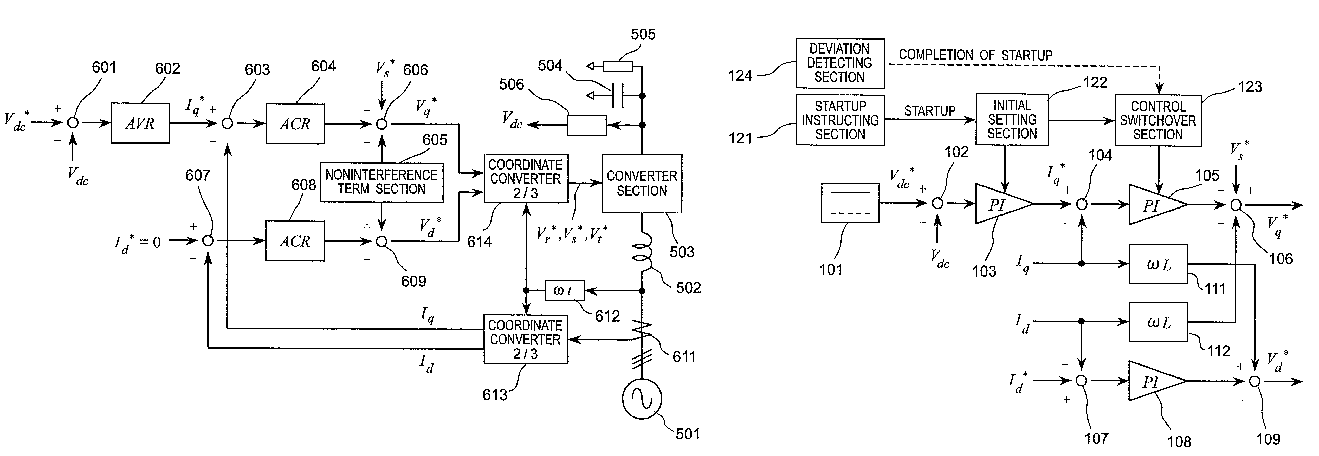
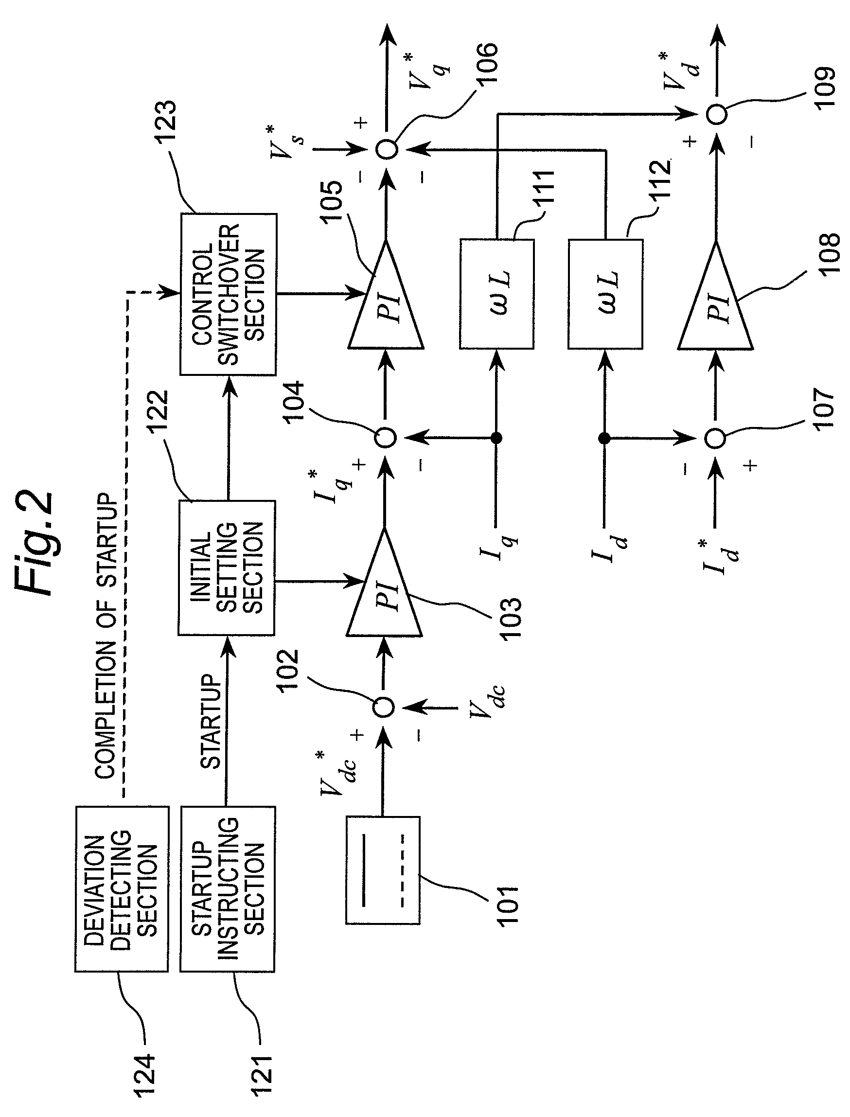
[0118]FIG. 2 shows a block diagram of the essential part of the control system of a current control type converter according to the first embodiment of the invention.

[0119]As shown in FIG. 2, the current control type converter includes a DC voltage instructing section 101 that outputs a DC voltage instruction value Vdc*, an adder-subtractor 102 that subtracts a DC voltage value Vdc from the DC voltage instruction value Vdc* from the DC voltage instructing section 101, a PI controller 103 that serves as one example of the voltage controller for calculating and outputting an active current instruction value Iq* by proportional-plus-integral control to perform proportional integration of a deviation between the DC voltage instruction value Vdc* outputted from the adder-subtractor 102 and the DC voltage value Vdc, an adder-subtractor 104 that subtracts an active current Iq from the active current instruction value Iq* from the PI controller 103, a PI controller 105 that serves as one ex...

second embodiment

[0127]FIG. 4 shows a block diagram of the essential part of the control system of a current control type converter according to the second embodiment of the invention.

[0128]As shown in FIG. 4, the current control type converter includes a DC voltage instructing section 201 that outputs a DC voltage instruction value Vdc*, an adder-subtractor 202 that subtracts a DC voltage value Vdc from the DC voltage instruction value Vdc* from the DC voltage instructing section 201, a PI controller 203 that serves as one example of the voltage controller for calculating and outputting an active current instruction value Iq* by proportional-plus-integral control to perform proportional integration of a deviation between the DC voltage instruction value Vdc* outputted from the adder-subtractor 202 and the DC voltage value Vdc, an adder-subtractor 204 that subtracts an active current Iq from the active current instruction value Iq* from the PI controller 203, a PI controller 205 that serves as one e...

third embodiment

[0135]FIG. 6 shows a block diagram of the essential part of the control system of a current control type converter according to the third embodiment of the invention.

[0136]As shown in FIG. 6, the current control type converter includes a DC voltage instructing section 301 that outputs a DC voltage instruction value Vdc*, an adder-subtractor 302 that subtracts a DC voltage value Vdc from the DC voltage instruction value Vdc* from the DC voltage instructing section 301, a PI controller 303 that serves as one example of the voltage controller for calculating and outputting an active current instruction value Iq* by proportional-plus-integral control to perform proportional integration of a deviation between the DC voltage instruction value Vdc* outputted from the adder-subtractor 302 and the DC voltage value Vdc, an adder-subtractor 304 that subtracts an active current Iq from the active current instruction value Iq* from the PI controller 303, a PI controller 305 that serves as one ex...


PUM


Abstract

A current control type converter has a converter section and a control section that includes three controllers. A first controller calculates and outputs an active current instruction value by proportional-plus-integral control to perform proportional integration of a deviation between the value of a DC voltage outputted from the converter section and a DC voltage instruction value. A second controller calculates and outputs an active voltage correction value by proportional-plus-integral control to perform proportional integration of a deviation between the active current instruction value from the first controller and the value of an active current inputted to the converter section. A third controller calculates and outputs a reactive voltage correction value by proportional-plus-integral control to perform proportional integration of a deviation between the value of a reactive current inputted to the converter section and a reactive current instruction value.

Description

CROSS-REFERENCE TO RELATED APPLICATIONS[0001]This U.S. National stage application claims priority under 35 U.S.C. §119(a) to Japanese Patent Application No. 2006-230302, filed Aug. 28, 2006, the entire contents of which are hereby incorporated herein by reference.TECHNICAL FIELD[0002]The present invention relates to current control type converters and, in particular, to a current control type converter that has a converter section to convert a three-phase AC voltage into a DC voltage.BACKGROUND ART[0003]Conventionally, there has been a current control type converter that has a converter control system using current control by the dq axis (refer to, for example, JP3192058).[0004]The current control type converter controls the DC voltage constant by using a q-axis current as an active component, using a p-axis current as a reactive component and controlling the active component by an active current instruction value on the basis of the deviation of the voltage controller for the DC vo...

Claims


Application Information

Patent Timeline
Patent Type & Authority Patents(United States)
IPC IPC(8): H02M1/00H02M7/757
CPCH02M7/219H02M1/32H02M1/36
Inventor SAKAKIBARA, KENICHI
Owner DAIKIN IND LTD
Why Eureka
Try Eureka