Neural stimulation delivery device with independently moveable delivery structures

a delivery device and delivery structure technology, applied in the field of neural stimulation delivery devices with independently moveable delivery structures, can solve the problems of not providing an optimal alternative, difficult to overcome these problems, and unable to sub-serve the desired function to be modulated

Active Publication Date: 2010-11-09
THE CLEVELAND CLINIC FOUND
View PDF26 Cites 57 Cited by
  • Summary
  • Abstract
  • Description
  • Claims
  • Application Information

AI Technical Summary

Problems solved by technology

Such precise targeting to focus stimulation towards a specific location sub-serving the desired function to be modulated requires enormous time and effort.
Furthermore, often times the stimulation must be adjusted or redirected after the initial surgery as a result of sub-optimal placement, lead migration, disease progression, inefficacious treatment, undesirable side effects, neural plasticity, or histological changes of tissue surrounding the stimulation device.
With present multi-contact electrode devices, it is hard to overcome these problems since it is difficult to redirect stimulation after the initial surgery even though limited readjustments can be made by selecting a different contact combination, pulse rate, pulse width or voltage.
Stimulation devices have been described to purportedly address the deficiencies of these multi-contact electrode devices, but none provide an optimal alternative.
Because of the configuration of the electrodes, however, the distance of electrical stimulation in the radial direction is limited.
Therefore, the lead assembly may not be able to effect therapy to neural tissue sites located outside the assembly's radius of stimulation.
Because the leads only project from the distal end of the cannula, the area over which stimulation can be provided is limited.
Such readjustment may require a second surgery if the decision to reposition the device is made after the initial surgery, thereby increasing the risk of bleeding and damage to surrounding neural tissue and increasing the cost of the overall therapy.

Method used


Image

  • Neural stimulation delivery device with independently moveable delivery structures
  • Neural stimulation delivery device with independently moveable delivery structures
  • Neural stimulation delivery device with independently moveable delivery structures

Examples


Embodiment Construction

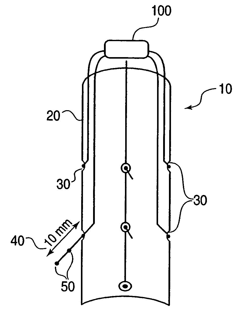
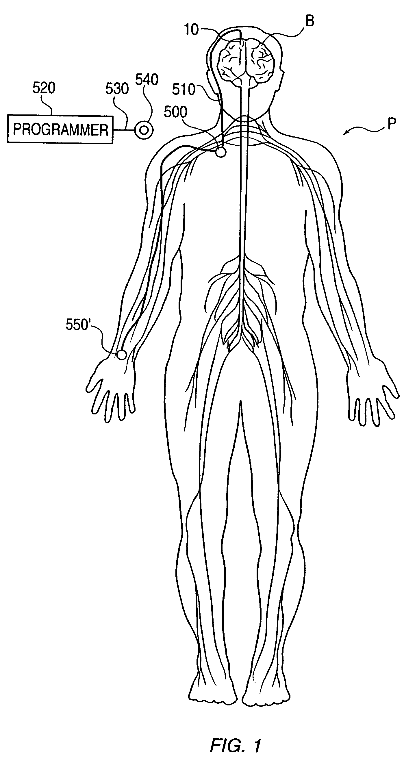
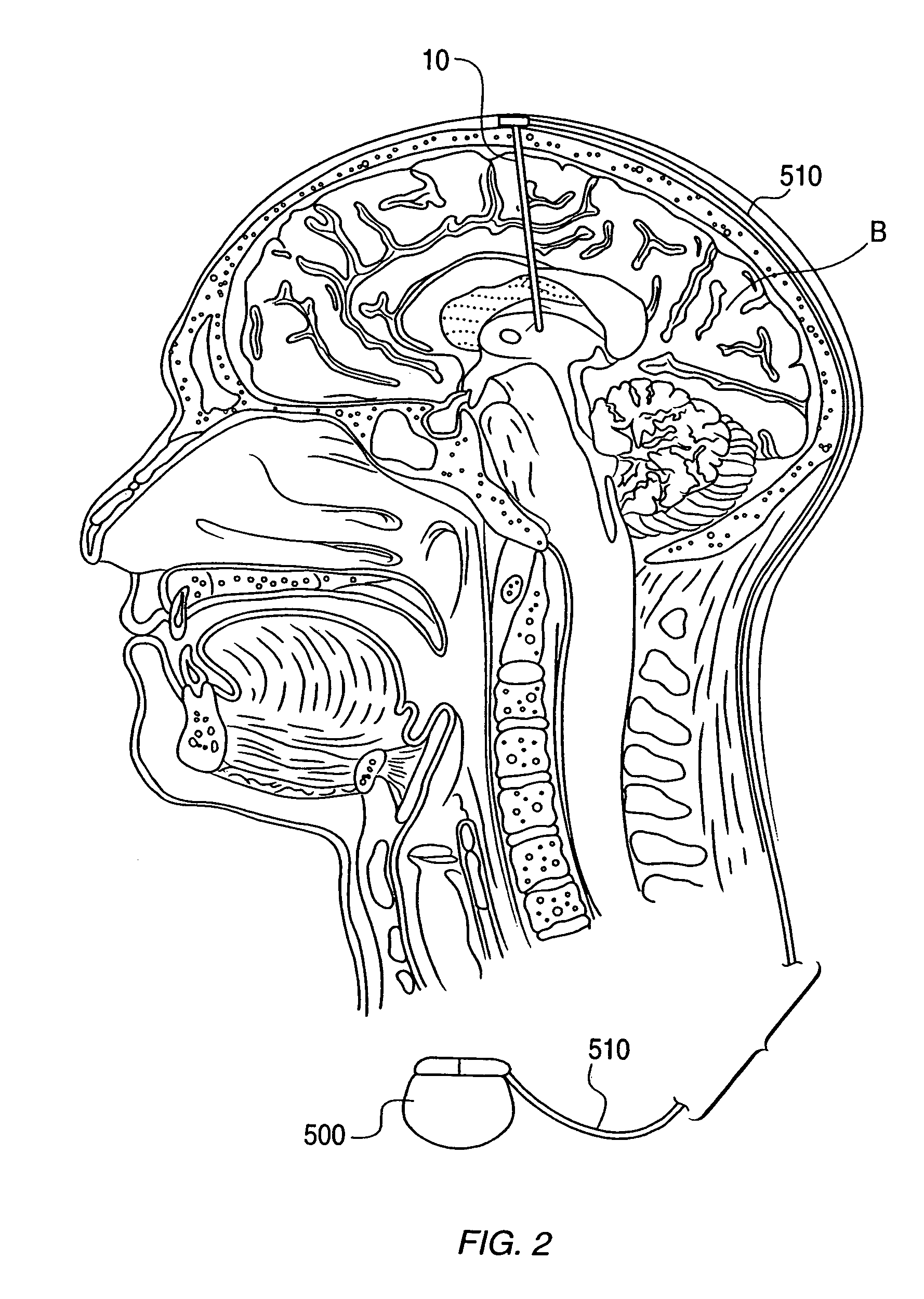
[0041]The present invention relates to a neural stimulator delivery device with independently moveable delivery structures. As illustrated diagrammatically in FIG. 1, device 10 may be implanted in brain B of patient P to modulate a neural tissue target site of brain B to affect a neurological condition. As illustrated schematically in FIG. 2, in a preferred system, device 10 is implanted within a target site of brain B and coupled to a therapy delivery device 500, such as a pulse generator or drug pump to produce electrical or chemical stimulation pulses that are sent to device 10 to electrically or chemically stimulate the target site. A connector 510, which is an insulated conductor in the case of electrical stimulation, couples therapy delivery device 500 to device 10. Therapy delivery device 500 is, in turn, implanted in the abdomen or any other part of a patient P's body.

[0042]With respect to general features and aspects of device 10 itself, referring to FIG. 3, device 10 inclu...


PUM


Abstract

The present invention relates to a neural stimulation delivery device to deliver electrical and / or chemical stimulation to target sites in the central and peripheral nervous system. The device generally includes a tubular body defining a plurality of ports along the longitudinal axis thereof, a plurality of delivery structures insertable in the body, and a control mechanism in communication with the plurality of delivery structures to independently move each of the plurality of delivery structures through a respective one of the plurality of ports with respect to each other of the plurality of delivery structures. The ability of each delivery structure to be independently moveable through a respective port allows each delivery structure to be selectively advanced or retracted independent of the movement of another delivery structure.

Description

CROSS-REFERENCE TO RELATED APPLICATIONS[0001]This is a 371 application of PCT / US03 / 02845 filed 31 Jan. 2003, the content of which is incorporated herein by reference.[0002]This application also claims priority to Provisional U.S. Application No. 60 / 353,705 filed Feb. 1, 2002, which is incorporated herein by reference.FIELD OF THE INVENTION[0003]The present invention relates to a device for electrically and / or chemically stimulating neural tissue.BACKGROUND OF THE INVENTION[0004]Electrical stimulation of neural tissue is becoming an increasingly preferred form of therapy for various neurological conditions and disorders. Such therapy provides distinct advantages over surgical lesioning techniques, which are still being used to affect disorders and conditions such as Parkinson's disease, essential tremors and dystonia. In particular, unlike surgical lesioning techniques, electrical stimulation is a reversible and adjustable procedure that provides continuous benefits as the patient's ...

Claims


Application Information

Patent Timeline
Patent Type & Authority Patents(United States)
IPC IPC(8): A61N1/372A61N1/05A61M25/01A61NA61N1/18A61N1/36
CPCA61N1/0531A61N1/0534A61N1/0539
Inventor REZAI, ALISHARAN, ASHWINI
Owner THE CLEVELAND CLINIC FOUND
Why Eureka
Try Eureka