
Exhaust purification system for internal combustion engine

a purification system and exhaust technology, applied in the direction of machines/engines, mechanical equipment, separation processes, etc., can solve the problems of reduced purification performance, reduced purification performance, and insufficient use of supplied fuel in the oxidation reaction of nox catalysts of storage-reduction type, and achieve more reliable nox reduction treatment

Inactive Publication Date: 2010-11-16
TOYOTA JIDOSHA KK
View PDF23 Cites 7 Cited by
  • Summary
  • Abstract
  • Description
  • Claims
  • Application Information

AI Technical Summary

Benefits of technology

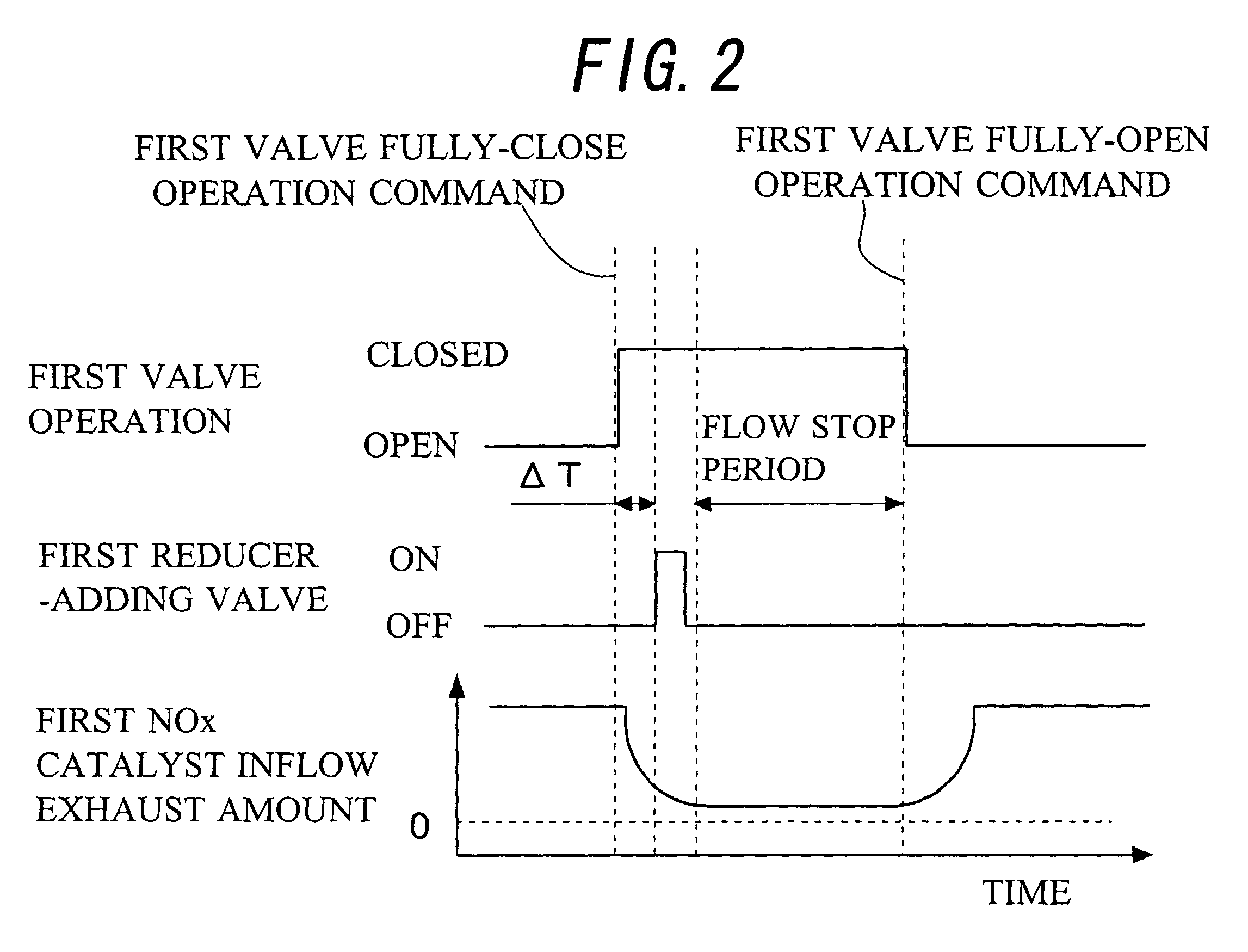
[0006]In an exhaust purification system for an internal combustion engine that reduces NOx stored in a storage-reduction type NOx catalyst by reducing an amount of exhaust flowing to the NOx catalyst and supplying a reducer to the NOx catalyst, it is an object of the present invention to provide art capable of performing more reliable NOx reduction treatment by controlling a dispersion of the reducer in the NOx catalyst.

Problems solved by technology

In the case of a storage-reduction type NOx catalyst used for this purpose, however, purification performance decreases as the amount of NOx stored increases.
It is also common knowledge that SOx in exhaust that is stored in the storage-reduction type NOx catalyst results in decreased purification performance, due to so-called SOx poisoning.
When supplying fuel that acts as a reducer to the storage-reduction type NOx catalyst, however, some of the supplied fuel may not be fully used in the oxidation reaction within the storage-reduction type NOx catalyst, if the amount of exhaust flow introduced to the storage-reduction type NOx catalyst is not appropriate.
This means that the NOx reduction treatment and the SOx poisoning recovery treatment may not be adequately performed, and fuel efficiency may also decrease.
However, the dispersibility of the added fuel remains poor in the above cases, and the fuel may tend to concentrate at a portion of the NOx catalyst.
Even when the fuel-adding timing is controlled based only on the state quantity of exhaust gas downstream of the NOx catalyst, there is a limit in such cases as to how much the dispersibility of the added fuel in the NOx catalyst can be raised.

Method used


Image

  • Exhaust purification system for internal combustion engine
  • Exhaust purification system for internal combustion engine
  • Exhaust purification system for internal combustion engine

Examples


first embodiment

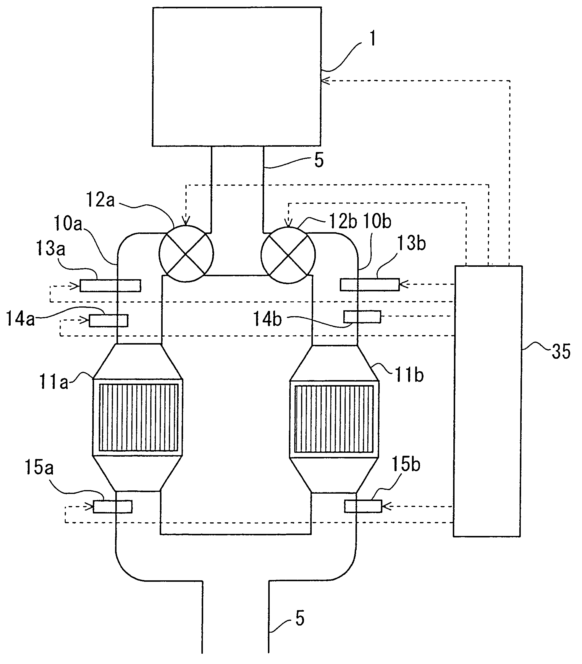
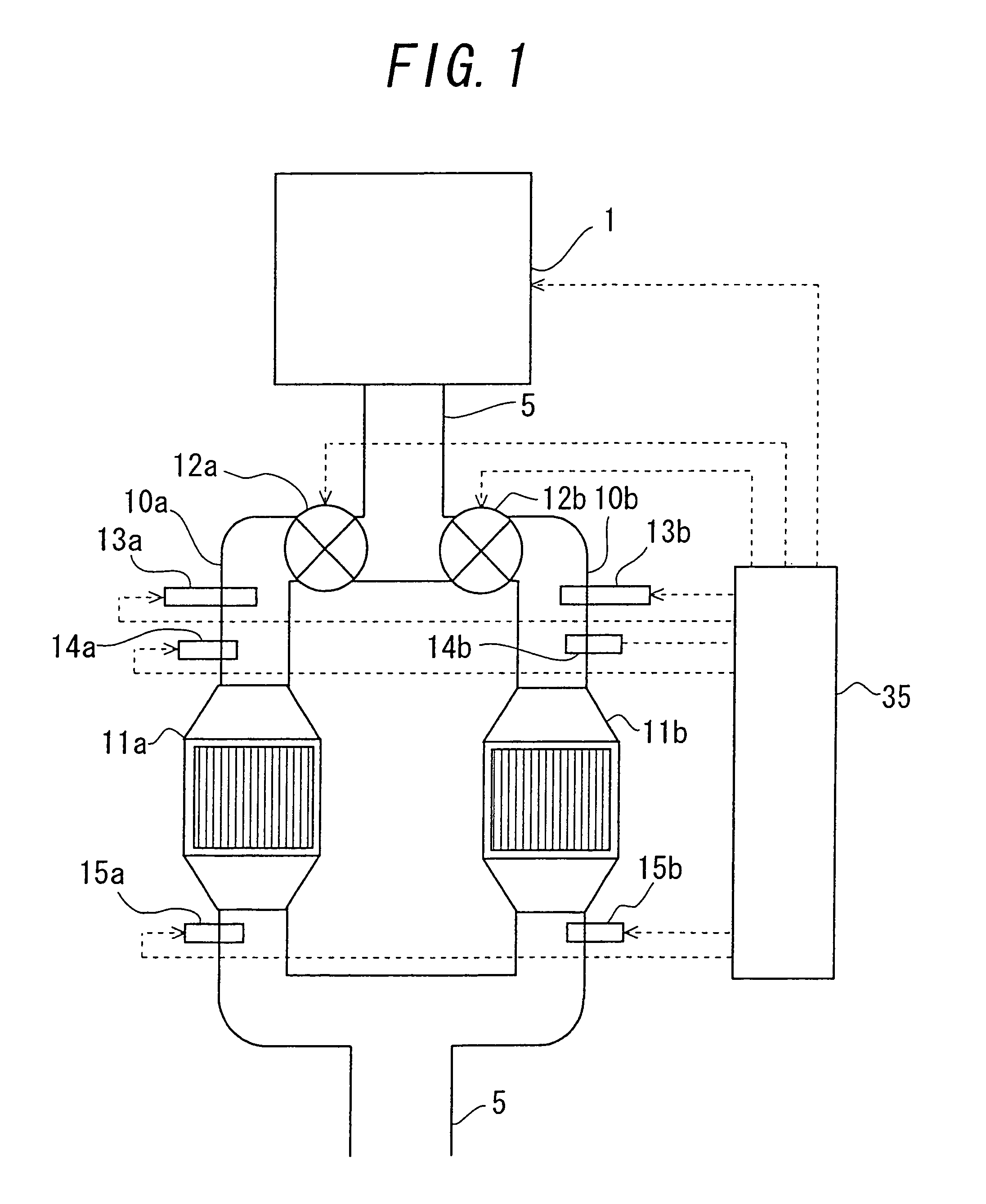
[0055]FIG. 1 is a view showing a schematic configuration of an internal combustion engine, and an exhaust system and a control system thereof, according to a first embodiment of the present invention. Note that the inside of an internal combustion engine 1 and an intake system thereof are omitted in FIG. 1.

[0056]Referring to FIG. 1, the internal combustion engine 1 is connected with an exhaust pipe 5 to which exhaust is distributed from the internal combustion engine 1. The exhaust pipe 5 is connected downstream with a muffler (not shown). In addition, the exhaust pipe 5 branches into a first branch passage 10a and a second branch passage 10b. The first branch passage 10a and the second branch passage 10b meet downstream. The first branch passage 10a is provided with a first NOx catalyst 11a, which stores and reduces NOx in the exhaust, while the second branch passage 10b is provided with a similar second NOx catalyst 11b.

[0057]Also provided in the first branch passage 10a is a fir...

second embodiment

[0112]Next, a second embodiment according to the present invention will be described. For the second embodiment, it is assumed that the value of the added fuel amount F, which is added from the first fuel-adding valve 13a, is preset to a constant value. A control will be described below that determines during the NOx reduction treatment explained in the first embodiment that the fuel added from the first fuel-adding valve 13a is excessively dispersing concentrated at a central portion in the first NOx catalyst 11a, and not dispersing toward portions on the upstream side and downstream side in the first NOx catalyst 11a. Such a determination is made instead determining that the added fuel amount F from the first fuel-adding valve 13a has deviated from an optimum value. In addition, such a determination is made if the absolute value of the deviation between the target air-fuel ratio AFT and the average value of the output AFT of the first upstream-side air-fuel ratio sensor 14a and th...

third embodiment

[0120]Next, a third embodiment according to the present invention will be described. The third embodiment is an example where a plurality of NOx catalysts is provided in series in the first branch passage 10a and the second branch passage 10b. The following description regards performing the NOx reduction treatment for the NOx catalysts provided in, for example, the first branch passage 10a. In this example, a target value of a difference between the output signals of the first upstream-side air-fuel ratio sensor 14a and the first downstream-side air-fuel ratio sensor 15a is set in accordance with an amount of reducer required for each NOx catalyst.

[0121]FIG. 9 shows a schematic configuration of the internal combustion engine 1, and the exhaust system and the control system thereof, according to the present embodiment. FIG. 9 is different from FIG. 1 in that: a first downstream-side NOx catalyst 16a, which is an auxiliary storage-reduction type NOx catalyst, is provided between the ...


PUM

PropertyMeasurementUnit
concentrationaaaaaaaaaa
lengthaaaaaaaaaa
travel speedaaaaaaaaaa

Abstract

Art is provided for an exhaust purification system for an internal combustion engine, which decreases an amount of exhaust flowing to a storage-reduction type NOx catalyst and supplies a reducer to the NOx catalyst so as to reduce NOx stored in the NOx catalyst, wherein the manner in which the reducer is dispersed in the NOx catalyst can be controlled to achieve more reliable execution of a NOx reduction treatment. Air-fuel ratio detecting unit is disposed upstream and downstream of the storage-reduction type NOx catalyst. During a predetermined period subsequent to decreasing an amount of exhaust flowing to the NOx catalyst and adding the reducer to the exhaust, a reducer-adding timing is changed such that a difference between an air-fuel ratio detected by the air-fuel ratio detecting unit disposed upstream of the NOx catalyst and an air-fuel ratio detected by the air-fuel ratio detecting unit disposed downstream of the NOx catalyst becomes a predetermined target value.

Description

TECHNICAL FIELD[0001]The present invention relates to an exhaust purification system for an internal combustion engine.BACKGROUND ART[0002]Normally NOx and other harmful substances are contained in exhaust gas from internal combustion engines. A NOx catalyst is provided in the exhaust system of the internal combustion engine in order to purify NOx in the exhaust. In the case of a storage-reduction type NOx catalyst used for this purpose, however, purification performance decreases as the amount of NOx stored increases. As a countermeasure, fuel that acts as a reducer is supplied to the storage-reduction type NOx catalyst so as to reduce and release NOx stored in the catalyst (hereinafter referred to as a “NOx reduction treatment”). It is also common knowledge that SOx in exhaust that is stored in the storage-reduction type NOx catalyst results in decreased purification performance, due to so-called SOx poisoning. Fuel that acts as a reducer is sometimes supplied to the storage-reduc...

Claims


Application Information

Patent Timeline
Patent Type & Authority Patents(United States)
IPC IPC(8): F01N3/00F01N3/10
CPCB01D53/9431F01N3/08F01N3/0807F01N3/206F01N13/011B01D2251/20Y02T10/24Y02T10/12
Inventor TOSHIOKA, SHUNSUKE
Owner TOYOTA JIDOSHA KK
Learn More