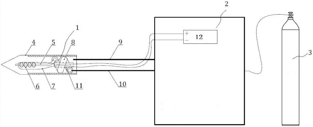
Cryoablation needle for achieving rewarming and thermotherapy functions through electrically heated wire
An electric heating wire and ablation needle technology, applied in the field of medical devices, can solve the problems of increasing the complexity of the host pipeline, unable to produce heating effect, difficult to pass radio frequency current, etc. Effect
- Summary
- Abstract
- Description
- Claims
- Application Information
AI Technical Summary
Problems solved by technology
Method used
Image
Examples
Embodiment 1
[0037] An example of adding an electric heating wire to the outside of the entire J-T slot is as follows: weld the two ends of the electric heating wire 6 to two wires 7 respectively, and use heat shrinkable tubes or insulating sleeves for insulation protection at the welding point 13. After the mandrel 11 is filled with glue, fold the wire in half at one of the soldering points 13, and then put the two wires 7 together into the mandrel until they reach the position of the other soldering point 13. After the glue solidifies, put the mandrel 7 into the finned tube 8, and then fix the front welding point 23 of the electric heating wire 6 on the front end of the J-T slot 5 with glue, and insert the J-T slot into the vacuum interlayer until it reaches the inside of the cutter head 4. Finally, connect the two wires 7 protruding from the mandrel to the positive and negative poles of the switching power supply 12 to form a heating current loop.
Embodiment 2
[0039] An example of folding the electric heating wire in half in the outer gap of the finned tube and then winding it side by side is as follows: weld the two ends of the electric heating wire 6 to two wires 7 respectively, and use heat shrinkable tube or insulating sleeve at the welding point 13 Do a good job of insulation protection, fold the electric heating wire 6 in half at the midpoint, then put it on the back end of the mandrel 11, wind it tightly along the gap between the finned tubes 11 until it reaches the front end of the finned tube 11, and fill the mandrel 11 After being filled with glue, put two wires 7 into the mandrel together, and stretch out from the mandrel rear end. After the glue solidifies, insert the J-T slot 5 and the finned tube 8 into the vacuum interlayer. Finally, connect the two wires 7 protruding from the mandrel to the positive and negative poles of the switching power supply 12 .
Embodiment 3
[0041] An example of placing an electric heating wire inside the air intake pipe and leading wires from the front and rear ends is as follows: the electric heating wire 6 is inserted into the air intake pipe 10, and both ends of the electric heating wire 6 protrude out of the air intake pipe 10 for a short section, and the two ends are respectively connected to the air intake pipe 10. The two wires 7 are welded, and the welding point 13 is insulated with a heat-shrinkable tube or an insulating sleeve. Take two lead-out tubes 15, fill them with glue, and then pass the wires 7 into one lead-out tube 15 Until the position of welding point 13 is reached. After the glue is solidified, fold the protruding two small sections of electric heating wire 6 toward the middle of the air intake pipe 10, insert the air intake pipe 10 and the outlet pipe 15 into the outer casing 17, and solder the rear end of the outer casing 17 to the air intake pipe. 10 and the junction of the outlet pipe 15...
PUM
 Abstract
Description
Claims
Application Information
 - R&D
- Intellectual Property
- Life Sciences
- Materials
- Tech Scout
- Unparalleled Data Quality
- Higher Quality Content
- 60% Fewer Hallucinations
Browse by: Latest US Patents, China's latest patents, Technical Efficacy Thesaurus, Application Domain, Technology Topic, Popular Technical Reports.
© 2025 PatSnap. All rights reserved.Legal|Privacy policy|Modern Slavery Act Transparency Statement|Sitemap|About US| Contact US: help@patsnap.com


