A biological wastewater inactivation system

A waste water and inactivation technology, applied in water treatment parameter control, heating water/sewage treatment, water/sludge/sewage treatment, etc. Efficient production operation, ensure heat dissipation, ensure the effect of inactivation effect

Active Publication Date: 2018-06-29
HUBEI HENGFENG MEDICAL PHARMA EQUIP CO LTD
View PDF11 Cites 0 Cited by
  • Summary
  • Abstract
  • Description
  • Claims
  • Application Information

AI Technical Summary

Problems solved by technology

[0003] The traditional treatment method for biological wastewater is physical sterilization. A biological wastewater inactivation system is formed by using one temporary storage tank and at least two inactivation tanks, and equipped with corresponding pipelines, pumps and valves. The basic principle is : Directly enter the active biological wastewater through steam, use high temperature to denature the bacterial cells or inactivate the coagulation enzyme to kill the bacteria, and the chemical bonds in the DNA and RNA of the virus will absorb heat over the years at high temperature, causing the bonds to break, thus making the virus lose active
[0004] However, the existing biological wastewater inactivation system has the following disadvantages: (1) It mainly uses manual operation of various valves and water pumps, and does not adopt an automatic operation mode. Energy saving and environmental protection, prone to damage operation and incomplete inactivation; (2) does not have real-time recording function, cannot record operating parameters to judge whether the system is in normal operation state, thus lacks safety guarantee; (3) inactivation tank When biological wastewater is inactivated at high temperature, the steam and biological wastewater cannot be fully contacted and mixed, which greatly affects the inactivation efficiency, and the biological wastewater lacks fluidity during the inactivation process, so it is easy to form scale in the inactivation tank. It takes a lot of time to descale and clean in the follow-up; (4) Whether it is a temporary storage tank or an inactivation tank, there is no dead-end design inside the tank, resulting in incomplete deactivation, especially in the sewage of the tank Due to the unreasonable installation position of the valve here, biological wastewater often remains in the pipeline from the sewage outlet to the valve, and this part of biological wastewater is difficult to inactivate by steam, so it is discharged from the sewage pipe to the next It is easy to cause secondary pollution after the first-grade sewage treatment system
(5) There is no tail gas treatment system on the temporary storage tank and the inactivation tank. When the gas in the tank is not thoroughly sterilized and discharged directly, it is easy to cause environmental pollution and pose a serious threat to people's life and health.

Method used


Image

  • A biological wastewater inactivation system
  • A biological wastewater inactivation system
  • A biological wastewater inactivation system

Examples


Embodiment Construction

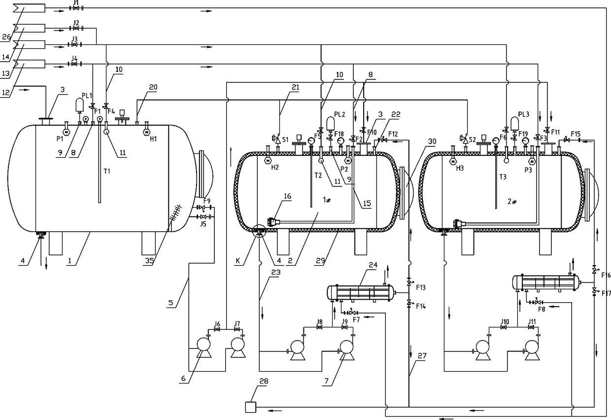
[0026] see Figure 1-2 , the present invention includes a temporary storage tank 1 and two deactivation tanks 2, wherein the two deactivation tanks 2 are respectively marked as 1# deactivation tank and 2# deactivation tank, and the two are used alternately, and the batch mode is adopted to run. Both the temporary storage tank 1 and the inactivation tank 2 are provided with a water inlet 3 and a sewage outlet 4, and a water delivery pipe 5 is set on the temporary storage tank 1 to communicate with the water inlet 3 on the two inactivation tanks, and the water delivery pipe 5 is provided with There are water inlet pumps 6, ball valves and pneumatic stop valves. The specific pipelines are as follows: water inlet pumps 6 are connected in parallel to form one for use and one for standby. Ball valves J6 and J7 are correspondingly installed on the pipelines where the two water inlet pumps are located. , on the water pipe 5 between the temporary storage tank 1 and the water inlet pum...


PUM

PropertyMeasurementUnit
heightaaaaaaaaaa
heightaaaaaaaaaa

Abstract

A biological wastewater inactivation system, including a temporary storage tank and at least two inactivation tanks, water inlets and sewage outlets are provided on the temporary storage tank and the inactivation tank, and water pipes are arranged on the temporary storage tanks to communicate with each The water inlet on the living tank, the temporary storage tank and the deactivation tank are all equipped with an air intake pipe, an exhaust pipe, a cleaning pipe and a cleaning device connected to the cleaning pipe. and disinfectant device, the inactivation tank is equipped with an "L"-shaped transfer pipe, one end of the "L"-shaped transfer pipe is connected to the air intake pipe, and the other end is equipped with a silent soda-water mixer; the temporary storage tank and the inactivation tank are also equipped with There are thermometers, pressure sensors and liquid level sensors, and are connected to the PLC controller by communication. The air intake pipe, exhaust pipe and cleaning pipe are equipped with pneumatic shut-off valves, and the PLC controller drives the connection to the water inlet pump and various pneumatic shut-off valves; The invention has the advantages of low operating cost, safety and reliability, complete inactivation, automatic control, and reduced labor intensity of workers.

Description

technical field [0001] The invention relates to the field of biological wastewater treatment, in particular to a biological wastewater inactivation system. Background technique [0002] At present, a large amount of active biological wastewater is produced in the experiment and production process of biopharmaceutical enterprises, laboratories or scientific research institutes. These biological wastewater contain a large number of surviving bacteria and viruses, which are very harmful and need to be processed After disinfection and sterilization treatment kills pathogens, it can be discharged into the next level of sewage treatment system. [0003] The traditional treatment method for biological wastewater is physical sterilization. A biological wastewater inactivation system is formed by using one temporary storage tank and at least two inactivation tanks, and equipped with corresponding pipelines, pumps and valves. The basic principle is : Directly enter the active biologi...

Claims


Application Information

Patent Timeline
Patent Type & Authority Patents(China)
IPC IPC(8): C02F1/02
CPCC02F1/02C02F2209/005C02F2303/14
Inventor 罗厚友
Owner HUBEI HENGFENG MEDICAL PHARMA EQUIP CO LTD
Why Eureka
Try Eureka