Torque wrench

a torque wrench and wrench body technology, applied in the field of torque wrenches, can solve the problems of difficult to reduce production costs, main components such as wrench bodies cannot be used in common, etc., and achieve the effects of preventing noise, facilitating tightening operation, and excellent usability

Active Publication Date: 2010-11-16
HOSIDEN CORP +1
View PDF18 Cites 23 Cited by
  • Summary
  • Abstract
  • Description
  • Claims
  • Application Information

AI Technical Summary

Benefits of technology

[0013]In a case of the torque wrench according to claim 1 of the present invention, when the effective lengths differ corresponding to ranges of tightening torques, it is possible to obtain accurate measurement results of tightening torques by changing the torque reference value corresponding to the effective value, basically. That is, it is possible to use main components other than the tightening unit for supplying various types of torque wrenches having different ranges of tightening torques. Therefore, the production cost can be suppressed.
[0014]In a case of the torque wrench according to claim 2 of the present invention, when performing tightening operation by holding the back side grip part of the housing by hand, the tightening force acts directly on the strain body only through the axis as long as the grip position is appropriate. That is, since the power point with respect to the strain body is one, it is possible to detect the tightening force with high accuracy by the distortion sensor, whereby the measurement accuracy of the tightening torque is improved.
[0016]In a case of the torque wrench according to claim 4 of the present invention, when the measured tightening torque is close to or reaches a tightening torque set value which has been set in advance, the fact is outputted. Therefore, it is possible to perform tightening operation smoothly.
[0017]In a case of the torque wrench according to claim 5 or 6 of the present invention, a lock mechanism for locking such that the back side grip part is capable of being unlocked without tilting with respect to the front side cover, therefore, when it is not used as a torque wrench, if it is locked such that the back side grip part does not tilt, it is possible to perform tightening operation other than a torque wrench. Further, if the back side grip part is locked, it is possible to prevent noise which may be caused when the back side grip part contacts the front side cover part or the like, thereby excellent usability can be obtained.

Problems solved by technology

However, in the case of the conventional example described above, a manufacturer is required to provide plural kinds of torque wrenches having different ranges of tightening torques, but if their effective lengths differ corresponding to the ranges of the tightening torques, main components such as a wrench body cannot be used in common.
This causes a problem that it is difficult to reduce the production cost.

Method used


Image

  • Torque wrench
  • Torque wrench
  • Torque wrench

Examples


Embodiment Construction

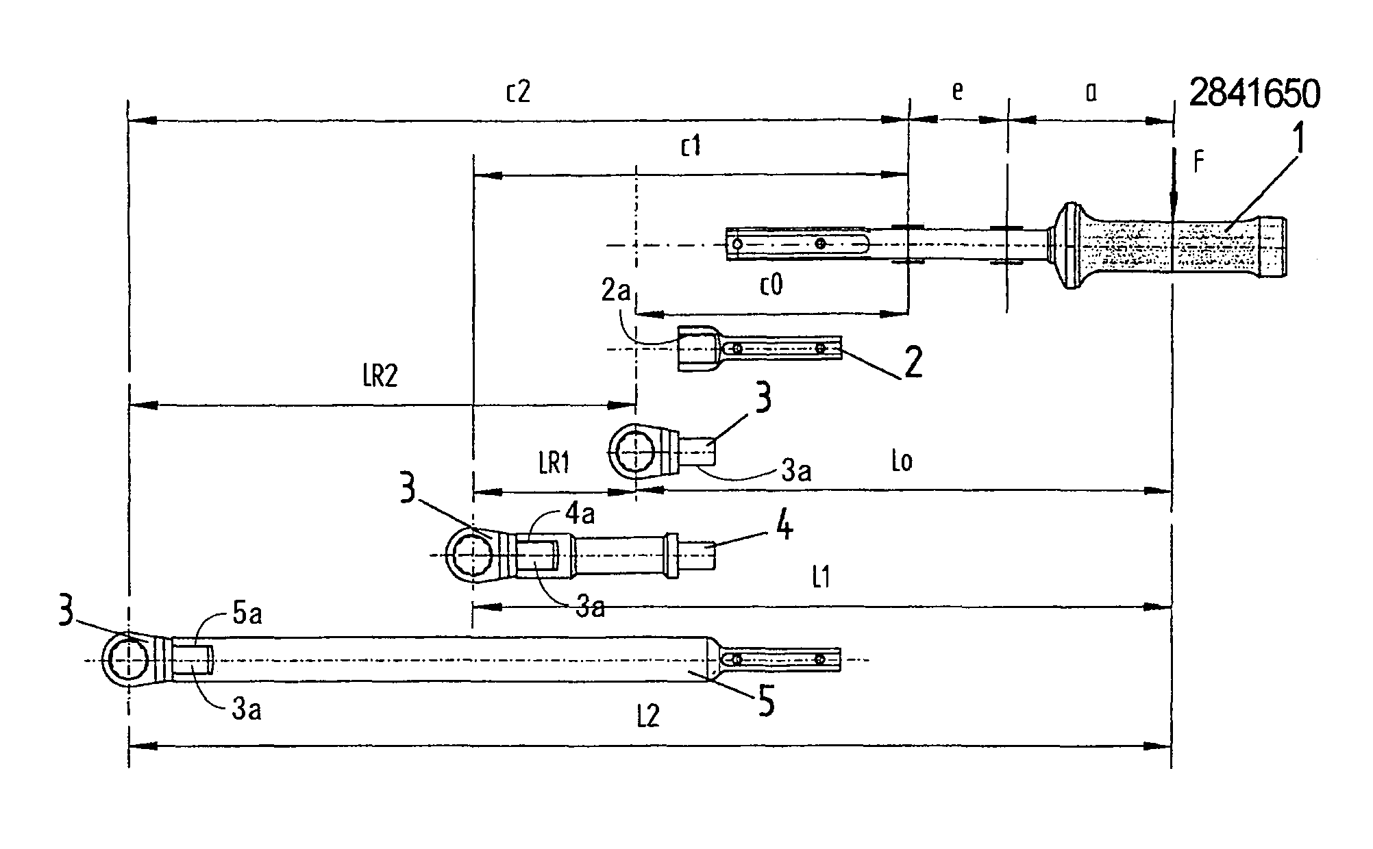
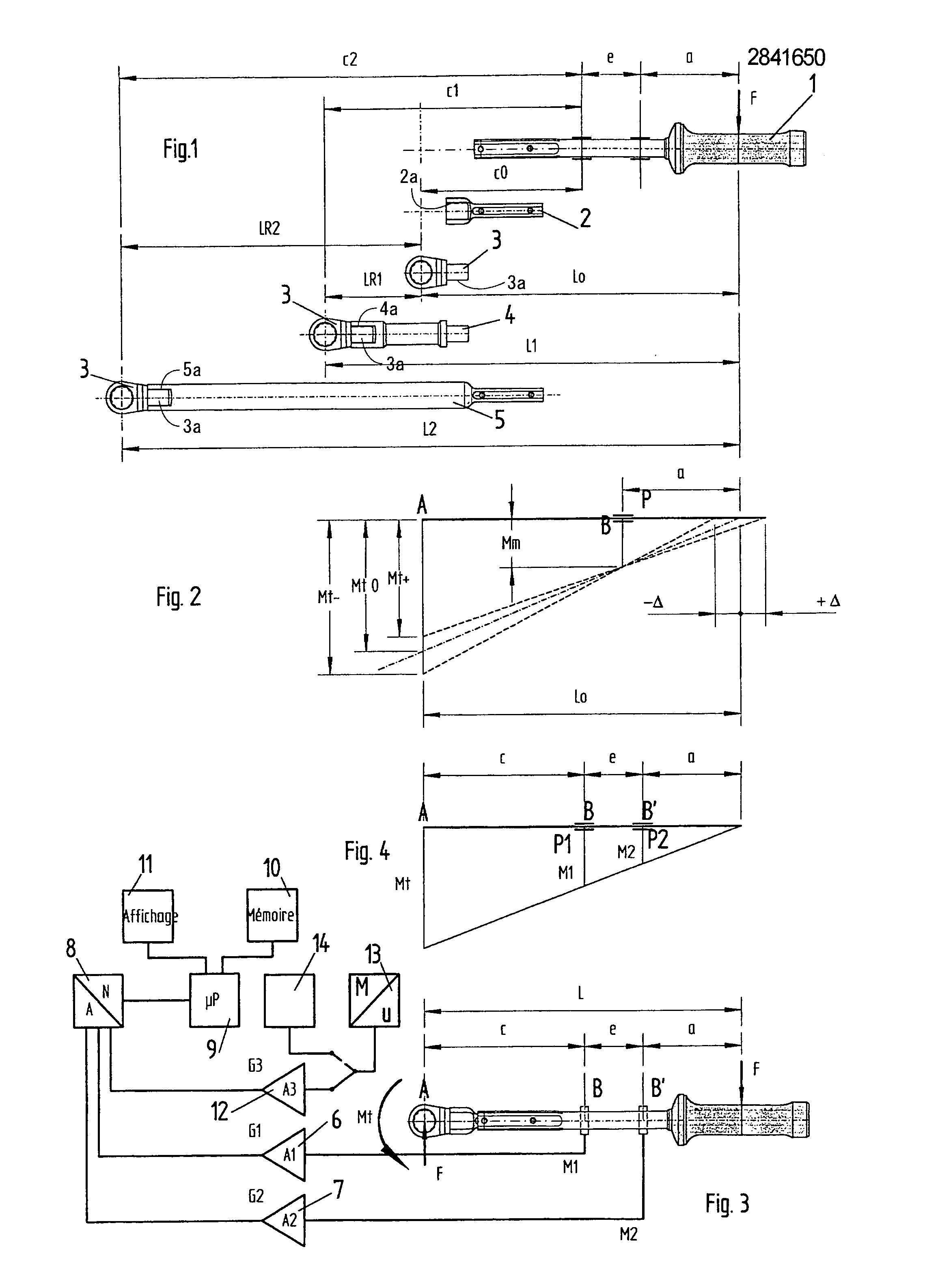
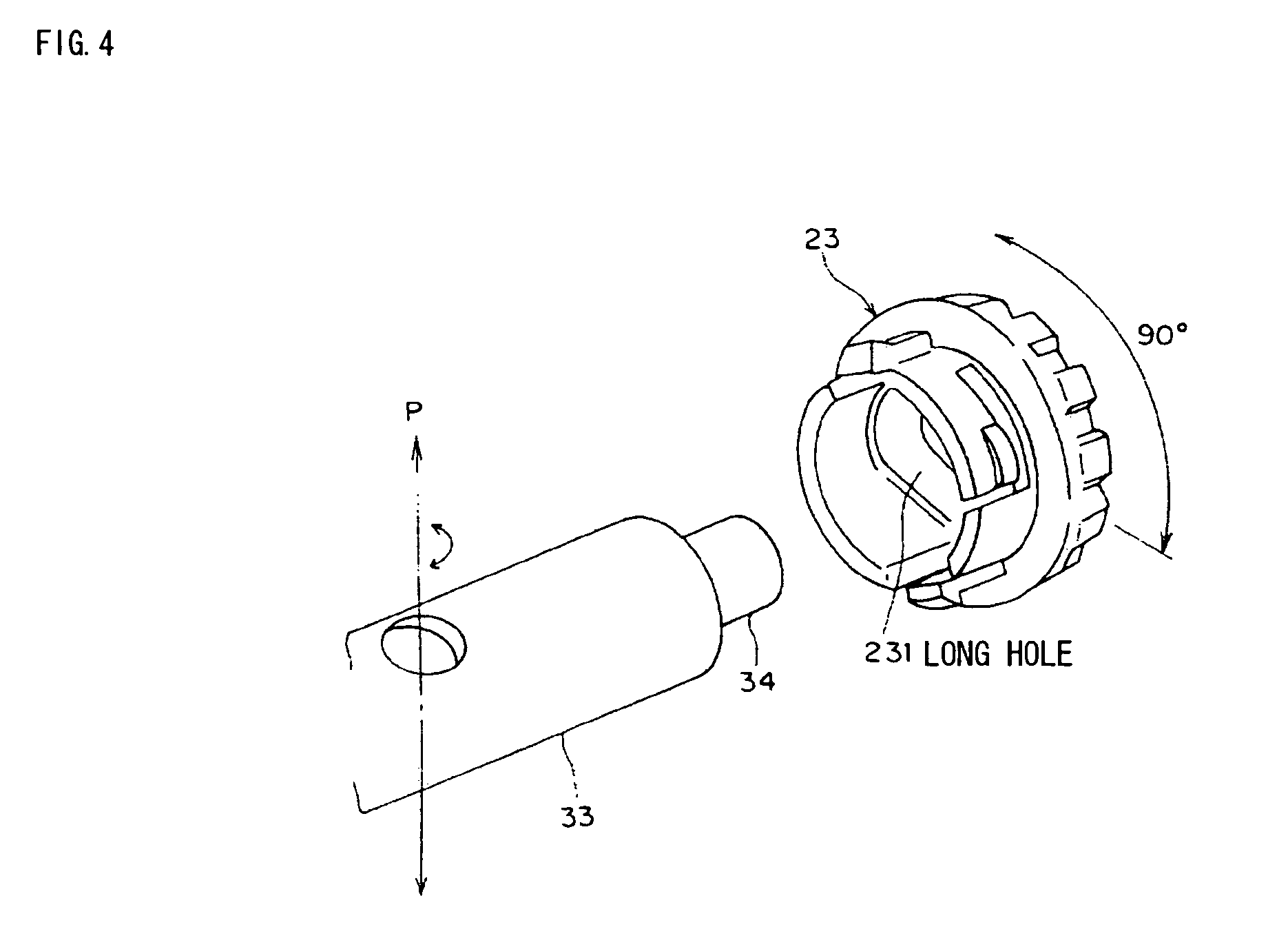
[0045]Hereinafter, an embodiment of the present invention will be explained with reference to FIGS. 1 to 8. FIG. 1 shows a front view and a side view of a torque wrench, FIG. 2 is a cross-sectional view taken along the line A-A in FIG. 1, FIG. 3 is a schematic diagram showing the internal structure of the torque wrench viewed from the front side, FIG. 4 is an exploded perspective view of a lock mechanism of the torque wrench, FIG. 5 is aback side view of a lock unit constituting the lock mechanism, FIG. 6 is an electrical block diagram of the torque wrench, FIG. 7 is a circuit diagram of a sensor unit of the torque wrench, and FIG. 8 is an illustration for showing a modification of a tilt detector, which is a schematic diagram showing the internal structure of a back side grip part of a torque wrench.

[0046]A torque wrench shown here is basically configured to include: a tightening unit 10 such as a ratchet; a housing 20 in a two-divided structure consisting of a front side cover par...


PUM

PropertyMeasurementUnit
tilt angleaaaaaaaaaa

Abstract

The invention seek to enable to share main components other than a tightening unit even in use for different effective lengths corresponding to ranges of tightening torques. There are provided: a tightening unit 10 such as a ratchet; a housing 20 having a two-divided structure including a front side cover part 21 and a back side grip part 22; a strain body 30 provided inside the housing 20 and replaceably coupling the tightening unit 10 thereto; a distortion sensor 40, provided to the strain body 30, for detecting the distorted amount of the strain body 30 due to the tightening force of the tightening unit 10; a microprocessor chip 100 having functions including computing the tightening torque of the tightening unit 10 based on torque reference values prepared in advance and detection results of the distortion sensor 40; and an output unit 300 for outputting such as the tightening torque.

Description

CROSS-REFERENCE TO RELATED APPLICATIONS[0001]The present invention claims priority under 35 U.S.C. [section] 119 of Japanese Patent Application No. JP 2005-111035 filed on Apr. 7, 2005, the disclosure of which is expressly incorporated by reference herein in its entirety.BACKGROUND OF THE INVENTION[0002]1. Field of the Invention[0003]The present invention relates to a torque wrench for measuring a tightening torque of a tightening tool such as a latchet by using a distortion sensor.[0004]2. Description of the Related Art[0005]In conventional torque wrenches, there is one in which a tightening tool such as a ratchet is fixed to the wrench main body, and a tightening torque is computed based on an output of a distortion sensor mounted on a handle part of the wrench main body, having a function that when the computation result reaches a tightening torque set value which has been set beforehand, an alarm or the like is generated, whereby an appropriate tightening torque can be obtained ...

Claims


Application Information

Patent Timeline
Patent Type & Authority Patents(United States)
IPC IPC(8): G01L5/24
CPCB25B23/1425
Inventor NAKAGAWA, TAKAMICHINAKATA, SHOGOUMEKAWA, MASAHIKOHANAI, TADASHIFUJITA, KOUJI
Owner HOSIDEN CORP
Why Eureka
Try Eureka