Spindle bracket of torsion beam axle suspension

a technology of torsion beam and axle suspension, which is applied in the direction of resilient suspension, interconnection system, vehicle components, etc., can solve the problems of deterioration of durability of welding portion, inability to achieve sufficient welding length in trailing arm 105, etc., to prevent the weight of the entire suspension system from increasing, and improve the durability of the entire spindle bracket.

Active Publication Date: 2010-11-16
HYUNDAI MOTOR CO LTD
View PDF8 Cites 5 Cited by
  • Summary
  • Abstract
  • Description
  • Claims
  • Application Information

AI Technical Summary

Benefits of technology

[0014]Various aspects of the present invention are directed to provide a spindle bracket of a torsion beam axle suspension system having advantages of increasing the welding length of the trailing arm so as to improve the durability thereof.
[0021]As stated above, in the spindle bracket of the torsion beam axle suspension system according to various aspects of the present invention that is configured as stated above, the first and second inner brackets are respectively fixed to the upper and lower portions of the end portion of the trailing arm, the inner side and the outer side of the trailing arm are welded, and the hub assembly is fixed to the outer bracket and the inner brackets by bolts such that the welding length to the trailing arm is increased to improve the durability of the entire spindle bracket.
[0022]Also, through the welding structure of the first and second inner brackets in various aspects of the present exemplary embodiment, the size of the entire spindle bracket is not increased to reinforce the durability thereof such that the weight of the entire suspension system is prevented from being increased, different from the conventional art.

Problems solved by technology

However, in the spindle bracket 103 of a torsion beam axle type suspension system according to the conventional art, as shown in FIG. 8, a welding portion (“A”) is formed along the end portion circumference at the outer surface of the trailing arm 105, such that sufficient welding length in the trailing arm 105 cannot be achieved and durability of the welding portion is deteriorated.

Method used


Image

  • Spindle bracket of torsion beam axle suspension
  • Spindle bracket of torsion beam axle suspension
  • Spindle bracket of torsion beam axle suspension

Examples


Embodiment Construction

[0031]Reference will now be made in detail to various embodiments of the present invention(s), examples of which are illustrated in the accompanying drawings and described below. While the invention(s) will be described in conjunction with exemplary embodiments, it will be understood that present description is not intended to limit the invention(s) to those exemplary embodiments. On the contrary, the invention(s) is / are intended to cover not only the exemplary embodiments, but also various alternatives, modifications, equivalents and other embodiments, which may be included within the spirit and scope of the invention as defined by the appended claims.

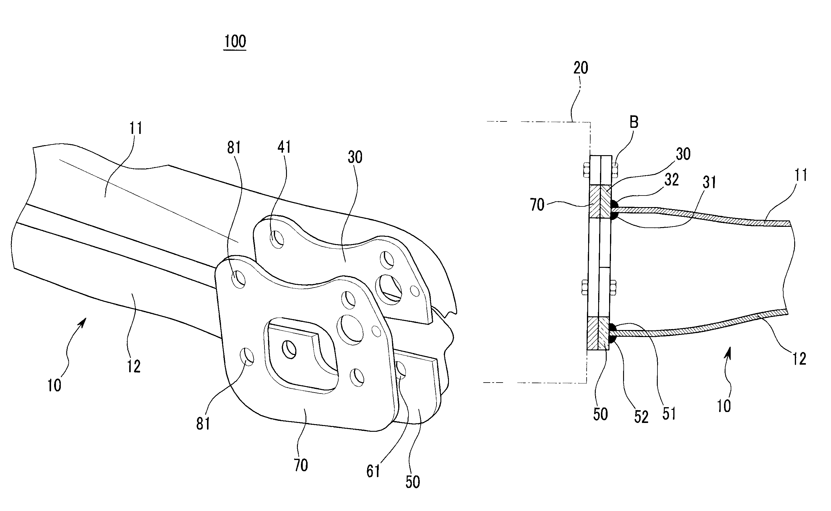
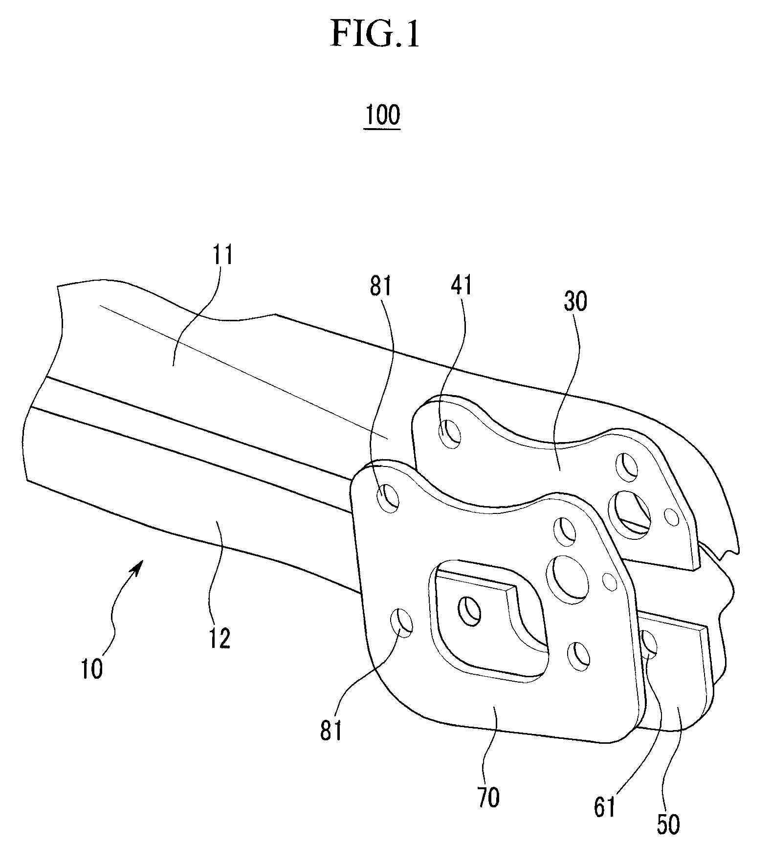
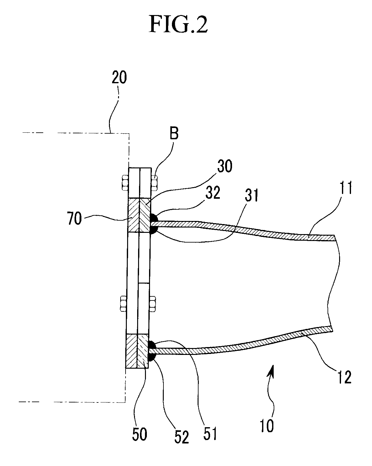
[0032]FIG. 1 is an exploded perspective view showing a spindle bracket of a torsion beam axle suspension system according to various embodiments of the present invention, and FIG. 2 is a sectional view showing the assembled condition of FIG. 1.

[0033]Referring to the drawings, a spindle bracket 100 of a suspension system of a torsion b...


PUM


Abstract

A spindle bracket of a torsion beam axle suspension system is defined on an end portion of a trailing arm to be connected to a hub assembly on which a wheel and a tire are mounted. The spindle bracket may include a first inner bracket that is welded to an inner side and an outer side of an end portion of a upper member of the trailing arm, a second inner bracket that is welded to an inner side and an outer side of an end portion of a lower member of the trailing arm, and an outer bracket that is attached to the first and second inner brackets to be engaged with the hub assembly in company with the first and second inner brackets.

Description

CROSS-REFERENCE TO RELATED APPLICATION[0001]The present application claims priority to Korean Patent Application Number 10-2008-0073236 filed on Jul. 25, 2008, the entire contents of which application incorporated herein for all purposes by this reference.BACKGROUND OF THE INVENTION[0002]1. Field of the Invention[0003]The present invention relates to a torsion beam axle suspension system. More particularly, the present invention relates to a spindle bracket of torsion beam axle suspension system having a structure in which a welding length of a trailing arm is increased.[0004]2. Description of Related Art[0005]Generally, even though the suspension system of a torsion beam axle type has simple components and narrow performance in a design, it has high driving stability compared to the low production cost and the light mass such that it can be mainly applied to a smaller car and a semi-mid-size car.[0006]In the suspension system of the torsion beam axle type, as shown in FIG. 6, a tor...

Claims


Application Information

Patent Timeline
Patent Type & Authority Patents(United States)
IPC IPC(8): B60G9/02
CPCB60G7/001B60G21/051B60G2206/201B60G2206/8201B60G2206/8207B60G11/18
Inventor LEE, WON JAE
Owner HYUNDAI MOTOR CO LTD
Why Eureka
Try Eureka